I/o connections, User controls – AJA RD5AD User Manual
Page 4
4
I/O Connections
FR1 and FR2 BNC Connector Assignments, RD5AD Card Module
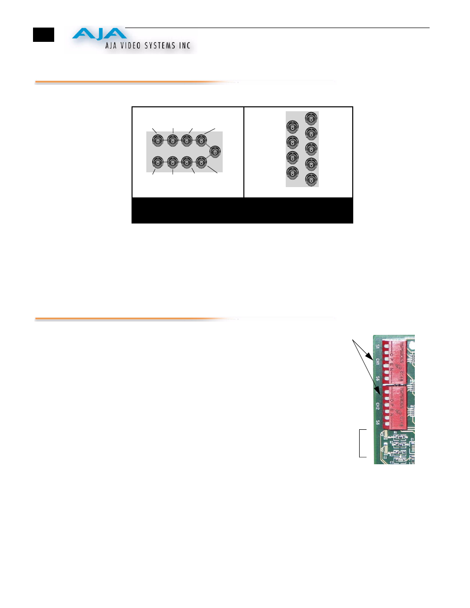
When the RD5AD module is installed in an AJA FR1 or FR2 frame, a corresponding
group of 9 BNCs on the rear panel then provide I/O for the module. The illustration
above shows the connector assignments for both the FR1 and FR2 when used with the
RD5AD.
User Controls
The user interface for the RD5AD includes two
dipswitches, a six-position for control of Channel 1 and
another for control of Channel 2. Two LEDs provide status
indication showing whether video is present at a respective
channel. The following table under “
Control Functions”
shows what each of the dipswitch positions perform. Both
dipswitches function identically for their respective
channels. The channel number is marked on the front of
the circuit card next to each dipswitch.
J1
J3
J5
J7
J9
J2
J4
J6
J8
J1
J2
J3
J4
J5
J6
J7
J8
J9
FR1 Frame Layout
RD5AD Rear Panel
FR2 Frame Layout
RD5AD Rear Panel
not used
G/Y/Comp
Channel 2
B/Pb
Channel 2
R/Pr/C
Channel 2
Serial Out
Channel 2
G/Y/Comp
Channel 1
B/Pb
Channel 1
R/Pr/C
Channel 1
Serial Out
Channel 1
not
used
G/Y/Comp
Channel 2
G/Y/Comp
Channel 1
B/Pb
Channel 2
B/Pb
Channel 1
R/Pr/C
Channel 2
Serial Out
Channel 2
R/Pr/C
Channel 1
Serial Out
Channel 1
Dipswitches
LEDs