I/o connections, Installation – AJA RD20DA User Manual
Page 4
4
I/O Connections
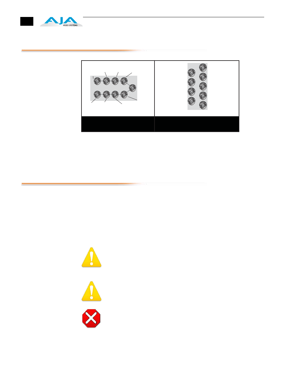
FR1 and FR2 BNC Connector Assignments, RD20DA Card Module
When the RD20DA module is installed in an AJA FR1 or FR2 frame, a
corresponding group of 9 BNCs on the rear panel then provide I/O for the
module. The illustration above shows the connector assignments for both the
FR1 and FR2 when used with the RD20DA.
Installation
Typically, RD20DA installation consists of the following:
1.
disconnect power from the frame (remove line cord)
2.
remove the FR1/FR2 front panel
3.
install RD20DA card module
4.
replace the FR1/FR2 front panel
5.
apply power to the frame by connecting a north american-style power
cord from the frame to mains power (90 to 260 VAC)
!
Warning!
Ensure Mains Power is disconnected before installing the FR1 or FR2 frame R-
series modules into the frame, or installing and removing options. If a Mains
switch is not provided, the power cord(s) of this equipment provide the
means of disconnection. The socket outlet must be installed near the
equipment and must be easily accessible.
Warning!
FR2 Dual Power Cord Notice—please read this. To reduce the risk of electrical
shock, disconnect both power cords before servicing equipment.
Caution!
The FR1/FR2 front fan door is heavy and is not hinged. Remove with Caution.
Instructions for removing the frame front door for module installation is
discussed in the
FR1/FR2 User Manual.
J1
J3
J5
J7
J9
J2
J4
J6
J8
J1
J2
J3
J4
J5
J6
J7
J8
J9
FR1 Frame Layout
RD20DA Rear Panel
FR2 Frame Layout
RD20DA Rear Panel
CH 1
SDI In
CH 1
SDI In
CH 1
Out 2
CH 1
Out 2
CH 1
Out 4
CH 1
Out 4
CH 2
Out 2
CH 2
Out 2
CH 2
SDI In 2
CH 2
SDI In 2
CH 1
Out 1
CH 1
Out 1
CH 1
Out 3
CH 1
Out 3
CH 2
Out 1
CH 2
Out 1
CH 2
Out 3
CH 2
Out 3