B&b electronics quick start guide, Attach rj45 cable (if equipped), Attach fiber optic cable – B&B Electronics Industrial Media Converter EIR102 User Manual
Page 2: Installation complete, Mechanical diagram, Fiber optic cable information
EIR102 1308qsg-2/2
© 2008 by B&B Electronics. All rights reserved.
International Headquarters:
707 Dayton Road PO Box 1040 Ottawa, IL 61350 USA
815-433-5100 Fax 433-5104 www.bb-elec.com [email protected] [email protected]
European Headquarters:
Westlink Commercial Park Oranmore Co. Galway Ireland
+353 91 792444 Fax +353 91 792445 www.bb-europe.com [email protected] [email protected]
B&B
ELECTRONICS
QUICK START GUIDE
Attach RJ45 Cable
(If equipped)
MDI Cable Pinout
Pin Signal
1 Tx+
2 Tx-
3 Rx+
6 Rx-
MDI-X Cable Pinout
Pin Signal
1 Rx+
2 Rx-
3 Tx+
6 Tx-
Attach Fiber Optic Cable
Warning: Work Safe – This is a Class I
Laser/LED device. To avoid causing
serious damage to your eyes, DO NOT
STARE DIRECTLY INTO THE LIGHT.
Installation Complete
1. When the network cables are attached and power
is applied, installation is complete.
NOTE: Recycle power if DIP Switch changes are
made after power up.
Female Connector
Mechanical Diagram
Fiber Optic Cable Information
Mode and Distance
Type
Wavelength
Multi-mode (2 km)
62.5/125 µm
1310 nm
Single-mode (15 km)
9/125 µm
1310 nm
Single-mode (40 km)
9/125 µm
1310 nm
Single-mode (80 km)
9/125 µm
1550 nm
Output Power
RCVR Sensitivity
Multi-mode (2 km)
-19 to -14 dBm
≤ -32 dBm
Single-mode (15 km)
-15 to -8 dBm
≤ -32 dBm
Single-mode (40 km)
-5 to 0 dBm
≤ -34 dBm
Single-mode (80 km)
-5 to 0 dBm
≤ -34 dBm
1. Auto MDI/MDI-x is
supported. A straight
through or cross-over
cable may be used.
2. 10/100BaseT auto
negotiation and full/half-
duplex are supported.
Speed and duplex can
also be forced. Refer to
DIP Switch settings.
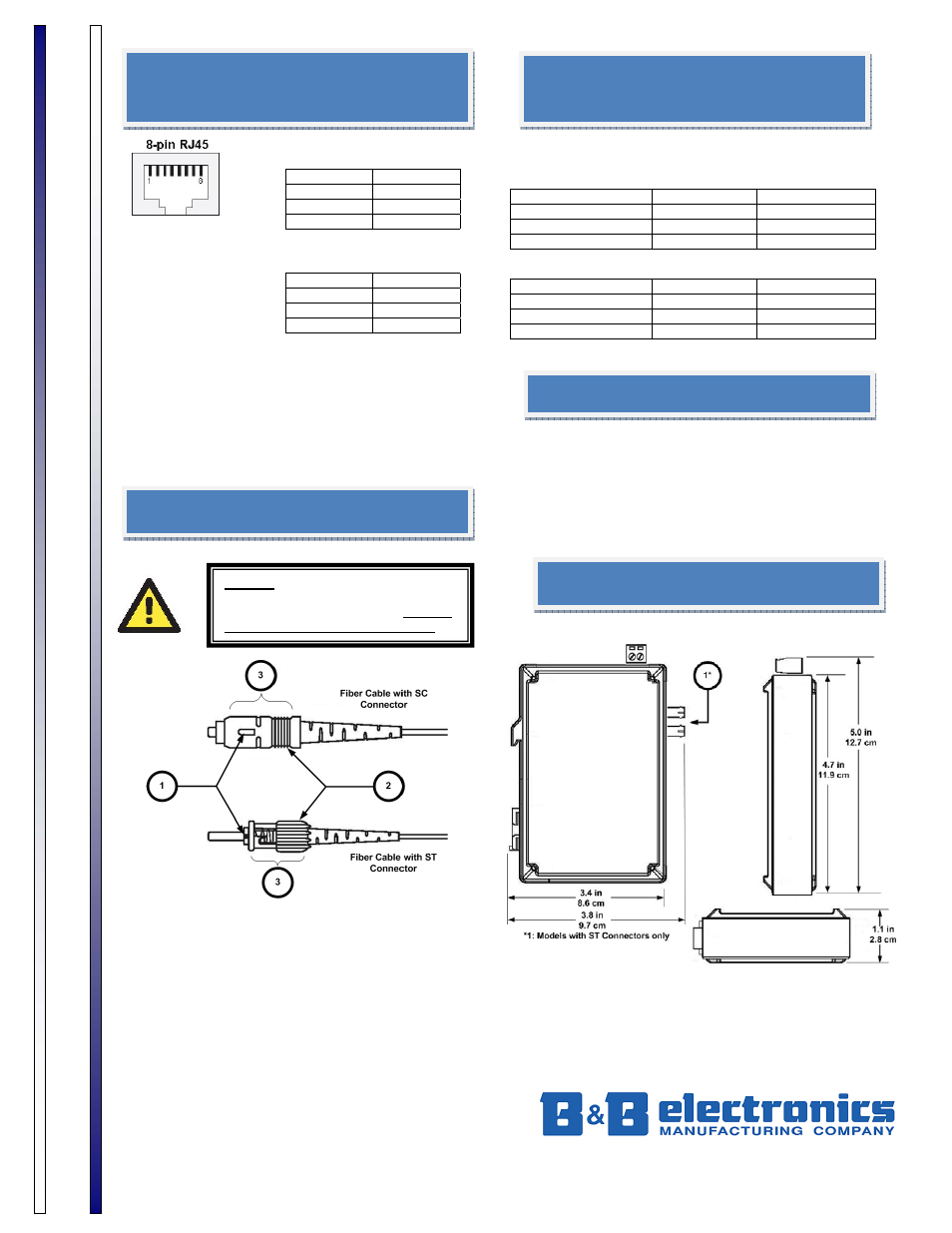
1.
Ensure your fiber optic cable is terminated with
the correct connector type. EIR102 Media
Converters use SC or ST connectors.
2.
Fiber optic type for each port is located on the
product’s side label. When connecting the cable
to the media converter, be sure to line up the
slider guide on the cable and media converter
connectors.
3.
Connect the fiber optic transmitter to the
downstream device’s receiver and vice-versa.
Fiber Optic Cable
Information