Assembly – Wood’s Powr-Grip LB10VLB User Manual
Page 4
Rev 0.1/12-12
2
LB10LVB: #35206AFT
ASSEMBLY
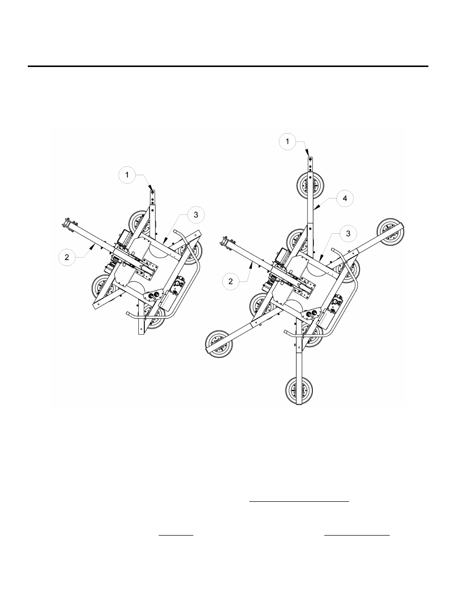
Before suspending the vacuum lifter from hoisting equipment as directed in the ASSEMBLY
section of the MRTALP lifter's instruction manual, assemble the Vertical Lift Bar in the appropriate
configuration for the intended use, as shown in the illustration. Note: Make sure the Vertical Lift
Bar is oriented so that the rubber bumper faces toward the load.
MRTALP-DC shown with Vertical Lift Bar option.
1 VERTICAL LIFT SPOOL INSERT
2 STANDARD LIFT BAR
3 PAD FRAME
4 VERTICAL LIFT BAR ASSEMBLY
Consult the INTENDED USE section of the MRTALP lifter's instruction manual to determine which
pad frame configuration is needed to support the load correctly. Be sure to assemble the
extended configuration of the Vertical Lift Bar (ie, the vertical lift bar assembly) whenever it is
required to position the hook point beyond the edge of the load. Then install the retaining bolts
and all associated hardware, making sure to tighten the bolts securely. Finally, attach the
hoisting equipment hook to the lift spool of the Vertical Lift Bar (
not
the standard lift bar).