Ift and, Ove the, About the tilt linkage – Wood’s Powr-Grip MRTA811LDCO User Manual
Page 18: About the optional tilt lock
Rev 0.0/6-14
16
MRTA8-DCO-DVS: #35077
T
O
L
IFT AND
M
OVE THE
L
OAD
About the Tilt Linkage
WARNING: Make sure load is positioned correctly on lifter; unbalanced loads
may tilt unexpectedly.
The lifter’s tilt linkage is designed to automatically hold a balanced load in either the upright or
the flat position. However, an unbalanced load may tilt unexpectedly from the flat position to the
upright position or vice versa, when lifted. This could result in load damage or injury to anyone
positioned in the tilt path of the load. To minimize the potential for these problems, make certain
prior to lifting any load
that it has allowable characteristics (see INTENDED USE: L
OAD
C
HARACTERISTICS
) and is attached correctly to the lifter (see T
O
A
PPLY THE
P
ADS TO A
L
OAD
preceding).
About the Optional Tilt Lock
When a lifter is equipped with a tilt lock, this option can be used to prevent tilt motion due to
wind loads or other unexpected forces. Since the tilt linkage normally holds a balanced load in
position, the tilt lock should only be needed if the operator cannot maintain control of the load
using the control handle or other appropriate means (such as when using the lifter to install glass
in multi-story buildings). The tilt lock is a secondary safety device and does not eliminate the
need to load the lifter correctly (see OPERATION: T
O
A
PPLY THE
P
ADS TO A
L
OAD
preceding).
CAUTION: Failure to load lifter correctly may damage tilt lock or other lifter
components.
The tilt lock can be set to engage automatically when the pad frame
reaches the vertical or horizontal position, or it can be deactivated,
depending on the application.
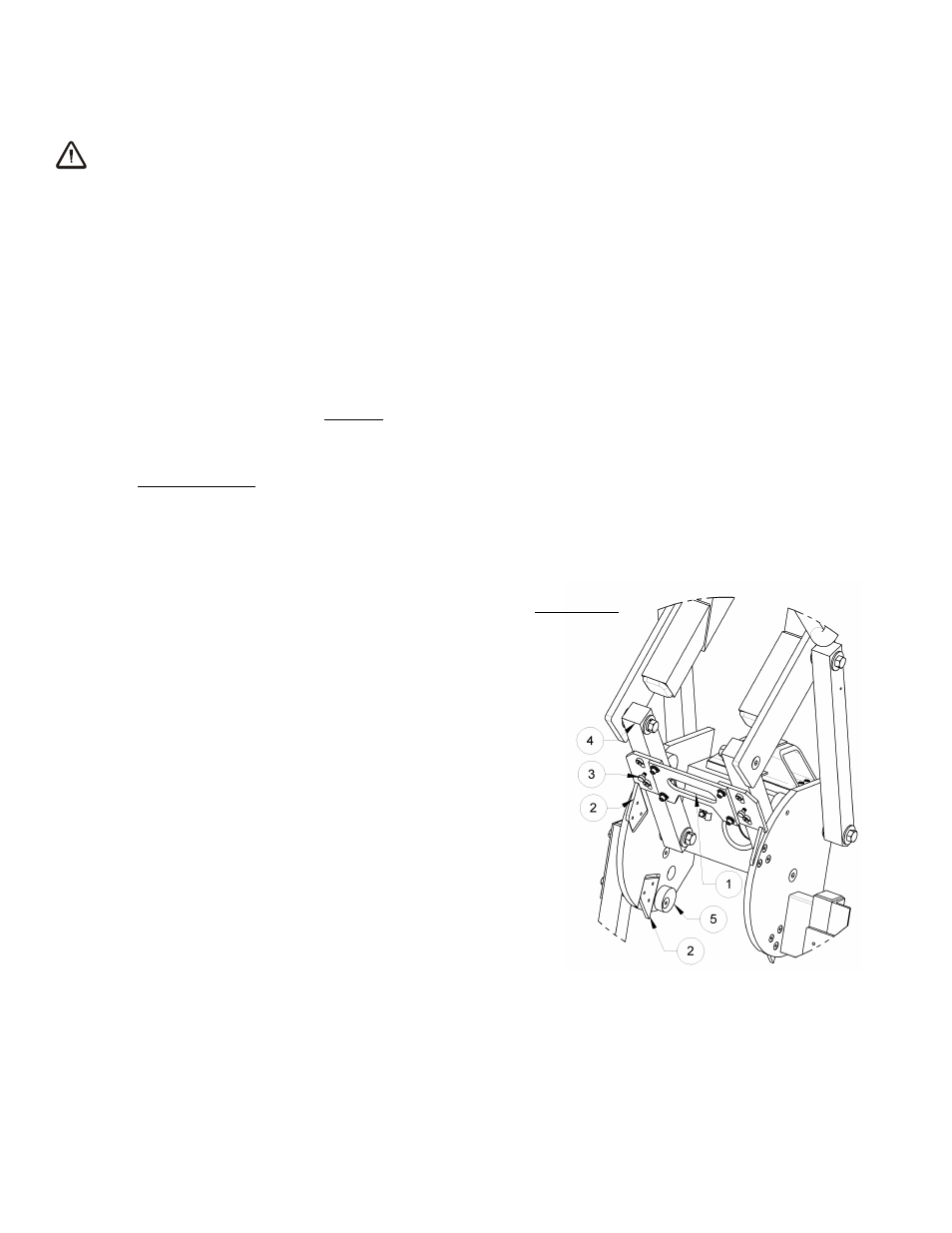
To Use the Tilt Lock
To allow automatic locking, make sure the lock handle/catch
plate assembly (#1) is set to slide up and lock behind the
lock ramp plates (#2) when the pad frame moves to either
the vertical or horizontal position. If not, pull outward on the
round knobs of the two spring plungers (#3) and turn them
90° to release the handle/catch plate assembly. Make sure
that the catch plates slide freely along the bars of the tilt linkage
(#4) before you attempt to tilt the pad frame. If the catch
plates do not lock behind the ramp plates or if the pad frame
exhibits excessive play in either the vertical or the horizontal
orientation, the stop cams (#5) for the tilt linkage may require
adjustment. Once the tilt lock is set to the automatic mode, simply
pull on the lock handle to disengage the lock.
To Deactivate the Tilt Lock
Make sure the lock handle/catch plate assembly (#1) is secured
so that it
cannot
lock behind the ramp plates (#2). If otherwise,
turn the round knobs of the spring plungers (#3) 90° and then
slide the lock handle/catch plate assembly upward until the spring plungers engage. Make sure
that the catch plates do not slide along the bars of the tilt linkage (#4).
1) LOCK HANDLE/CATCH PLATES
2) LOCK RAMP PLATE
3) SPRING PLUNGER
4) TILT LINKAGE
5) TILT STOP CAM