To connect/disconnect vacuum hoses – Wood’s Powr-Grip MRTALP611LDC User Manual
Page 12
Rev 10.0/5-14
10
MRTALP6-DC: #35056
Configurations are created by installing or removing the pad frame’s extension arms, by
repositioning or removing the movable pad mounts, and by connecting or disconnecting certain
vacuum pads, using the corresponding vacuum hoses.
Always assemble the pad frame in a
symmetrical arrangement
, to keep the lifter balanced (see examples in preceding illustration).
Note: The dual vacuum system is equipped with 2 air-line circuits, which are identified by color-
coded vacuum hoses. In order to ensure maximum effectiveness of the dual vacuum system,
the vacuum pads must be connected in an equal and alternating distribution to the 2 circuits, as
shown in the preceding illustration. Vacuum pads marked "1" belong to the first circuit and
vacuum pads marked "2" belong to the second circuit.
To support the maximum load weight, all vacuum pads must be installed on the pad frame and
the corresponding vacuum hoses must be connected to the vacuum system. To support the
largest load dimensions, all extension arms must also be installed on the pad frame. To support
smaller weights and dimensions, some extension arms or vacuum pads may be removed, and the
corresponding vacuum hoses may be disconnected,
provided that the lifter still has
sufficient capacity to support the load in question
.
WARNING: Removing or disconnecting any vacuum pad reduces load capacity
of lifter.
To calculate the load capacity when some vacuum pads are disconnected or removed, consult
the Per-Pad Load Capacity (see SPECIFICATIONS) and multiply by the number of pads currently
in use.
Note: Whenever a vacuum hose is disconnected from the vacuum system, the corresponding
vacuum pad does not contribute to the load capacity, whether or not the pad is mounted on the
pad frame.
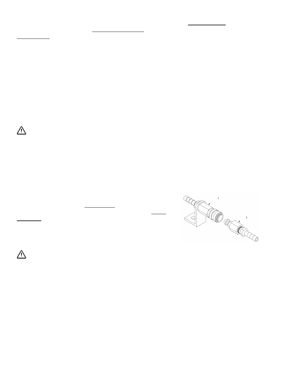
To Connect/Disconnect Vacuum Hoses
The vacuum hose for each vacuum pad is connected to or
disconnected from the vacuum system by means of a quick
connector. To connect the vacuum hose, push the male and
female ends of the connector together until they lock. To
disconnect the vacuum hose, move the release ring on the
female end away from the male end until the connector
separates.
WARNING: Make sure vacuum hoses are coiled or
routed to avoid damage during rotation or tilt.
Make sure all vacuum hoses are secure and routed to avoid being punctured, pinched, kinked,
entangled, abraded or otherwise damaged while the lifter is in operation.
QUICK CONNECTOR
1 FEMALE END
2 MALE END