How to use manual figures, Technical information, Engine components – Briggs & Stratton MS-5158-5/03 User Manual
Page 3: Hazard symbols and meanings, International symbols and meanings, Safety precautions
Document: - page 1 (Black)
Screen angle and frequency: 45.0000, 150.0000
GB
GB
1
Note: (This note applies only to engines used in the U.S.A.) Maintenance, replacement or repair of the emission control devices and systems may be performed
by any nonroad engine repair establishment or individual. However, to obtain no charge repairs under the terms and provisions of the Briggs & Stratton
warranty statement, any service or emission control part repair or replacement must be performed by a factory authorized dealer.
How To Use Manual Figures
-
refer to figures inside covers.
-
refer to engine components in figure
.
К
-
Т
refer to part/action in figures.
19
1
Record your engine Model, Type and Code numbers
here for future use.
Record your date of purchase here for future use.
In the state of California, OHV Model Series 290000,
300000 and 350000 engines are certified by the
California Air Resources Board to meet emissions
standards for 250 hours. Such certification does not
grant the purchaser, owner or operator of this engine
any additional warranties with respect to the perforĆ
mance or operational life of this engine. This engine is
warranted solely according to the product and emisĆ
sions warranties stated elsewhere in this manual.
Technical Information
POWER RATINGS: The power ratings for an individual
engine model are initially developed by starting with
SAE (Society of Automotive Engineers) code J1940
(Small Engine Power & Torque Rating Procedure) (ReĆ
vision 2002Ć05). Given both the wide array of products
on which our engines are placed, and the variety of enĆ
vironmental issues applicable to operating the equipĆ
ment, it may be that the engine you have purchased will
not develop the rated horsepower when used in a piece
of power equipment (actual onĆsite" power). This difĆ
ference is due to a variety of factors including, but not
limited to, the following: differences in altitude, temperĆ
ature, barometric pressure, humidity, fuel, engine luĆ
brication, maximum governed engine speed, individual
engine to engine variability, design of the particular
piece of power equipment, the manner in which the enĆ
gine is operated, engine runĆin to reduce friction and
clean out of combustion chambers, adjustments to the
valves and carburetor, and other factors. The power
ratings may also be adjusted based on comparisons to
other similar engines utilized in similar applications,
and will therefore not necessarily match the values deĆ
rived using the foregoing codes.
Engine Components
(see fig.
)
1 Air cleaner
2 Carburetor cover
3 Finger guard
4 Starter rope
5 Blower housing
6 Oil filter, if equipped
7 Spark plug wire
8 Rotating screen
9 Fuel pump
10 Spark arrester, if equipped
11 Exhaust manifold
12 Engine Model
Type
Code
xxxxxx xxxx xx xxxxxxxx
13 12V electric starter, if equipped
14 Oil fill/Dipstick
15 Oil drain plug
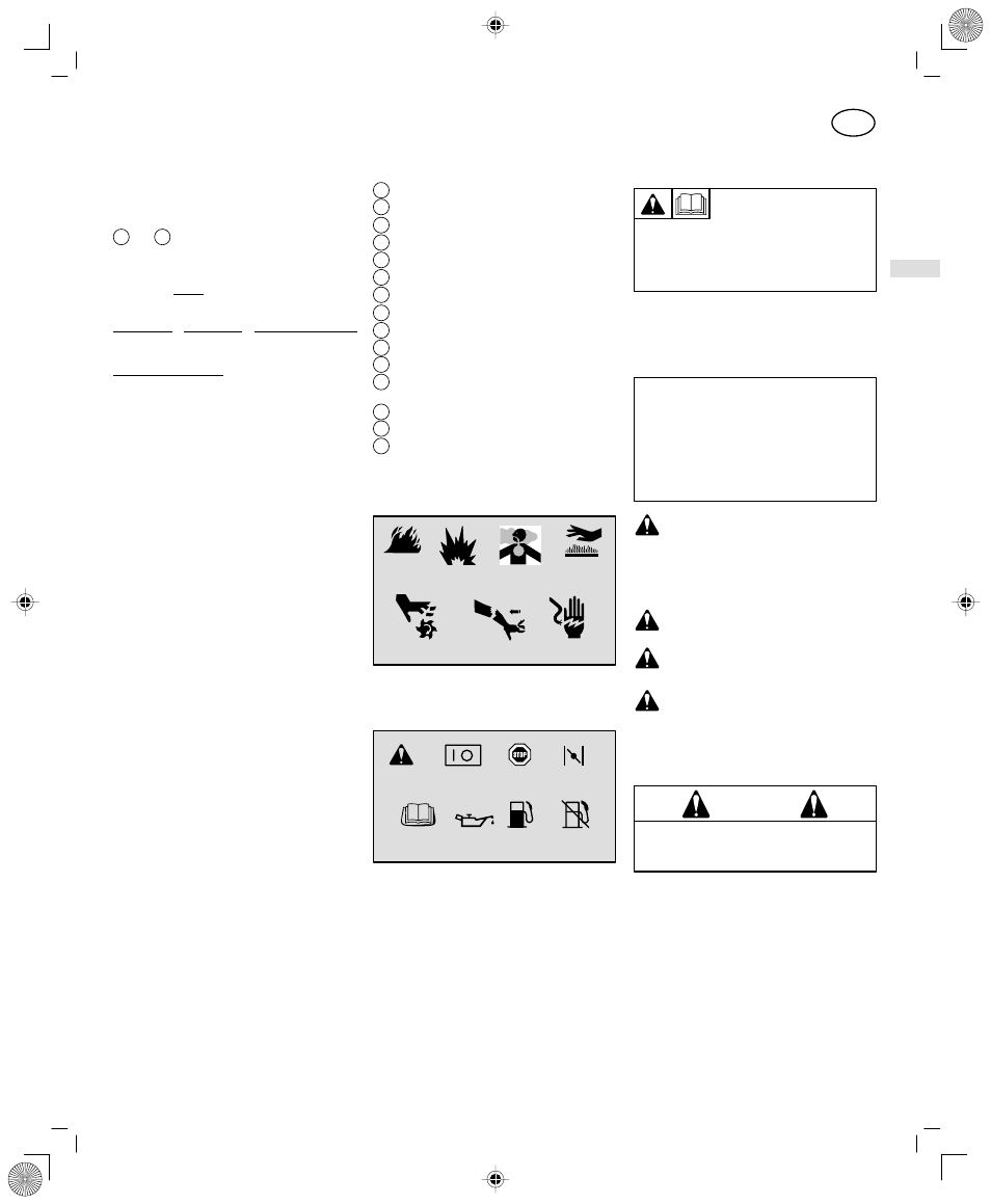
Hazard Symbols and Meanings
Explosion
Toxic Fumes
Moving Parts
Shock
Hot Surface
Kickback
Fire
International Symbols and Meanings
On Off
Fuel Shutoff
Read Owner's
Manual
Stop
Fuel
Choke
Safety Alert
Oil
Safety Precautions
* Briggs & Stratton does not necessarily know what
equipment this engine will power. For that reason,
you should carefully read and understand the
operating instructions for the equipment on which
your engine is placed.
BEFORE OPERATING ENGINE
• Read entire Operating & Maintenance Instructions
AND the instructions for the equipment this engine
powers.*
• Failure to follow instructions could result in serious
injury or death.
THE OPERATING & MAINTENANCE
INSTRUCTIONS CONTAIN SAFETY
INFORMATION TO
• Make you aware of hazards associated with engines
• Inform you of the risk of injury associated with those
hazards, and
• Tell you how to avoid or reduce the risk of injury.
The safety alert symbol is used to identify safety
information about hazards that can result in personal injury.
A signal word (DANGER, WARNING, or CAUTION) is used
with the alert symbol to indicate the likelihood and the potential
severity of injury. In addition, a hazard symbol may be used to
represent the type of hazard.
DANGER indicates a hazard which, if not avoided,
will result in death or serious injury.
WARNING indicates a hazard which, if not avoided,
could result in death or serious injury.
CAUTION indicates a hazard which, if not avoided,
might result in minor or moderate injury.
CAUTION
,
when used without the alert symbol,
indicates a situation that could result in damage to
the engine.
The engine exhaust from this product contains
chemicals known to the State of California to cause
cancer, birth defects, or other reproductive harm.
WARNING