Ultralife URB0003 User Manual
Page 7
MKM Multi-Kilowatt Module User Manual
Newark, New York | 315-332-7100 | Fax: 315-331-7800
©2013 Ultralife Corporation • www.ultralifecorp.com • All information is subject to change without notice.
The information contained herein is for reference only and does not constitute a warranty of performance. •
25 FEB 13 UBI-05342 Rev: -
Page 7 of 7
1. Power Connection
The main connector is an Anderson Power Products SB120 style power plug.
The mating plug has + / - labeled as to the correct orientation.
2. Ground Stud
There is a ground stud on the front panel to protect the panel from being
inadvertently energized, connect this stud to a known good ground.
3. Comm Port
The communication connector is a standard RJ45 connector. There are several
protocols being used in various versions of MKM. Initial versions have I2C
protocol as standard. Future models will have SMBus and CAN Bus, among
others. The Communication port is used for State of Charge and other internal
battery statuses.
Verify the version MKM you are using and the communication protocol before
proceeding. Please consult the factory for additional communications protocol
information.
The communication port requires an external +5/3VDC and Ground connection to
properly function. The port is fully isolated from the battery by an ADUM1250.
The pin out is as follows:
Pin 4 – I2C Data
Pin 5 – I2C Clock
Pin 7 - +5/3VDC
Pin 8 – Return (-)
Available registers are listed at the end of the Manual.
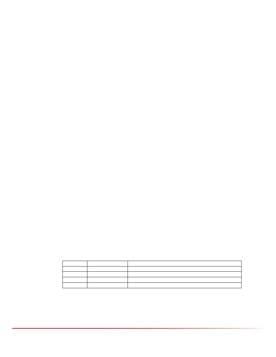
4. Status LED
The status LED provides information about the operational and error modes of
the MKM. The list of codes and meaning are present in the status table below:
COLOR FREQUENCY
STATE
GREEN
STEADY ON
OPERATING NORMALLY
RED
STEADY ON
FAULT CONDITION PRESENT
AMBER
STEADY ON
BATTERY IS FULLY CHARGED IN “FLOAT” MODE
NONE
NONE
BATTERY IS TURNED OFF
The status LED will turn red briefly before turning off when the circuit breaker is
cycled. This is normal.