Spaulding Lighting Cimarron CL1 LED User Manual
Page 2
OR
MAINTENANCE
WARNING:
DISCONNECT POWER BEFORE INSTALLATION
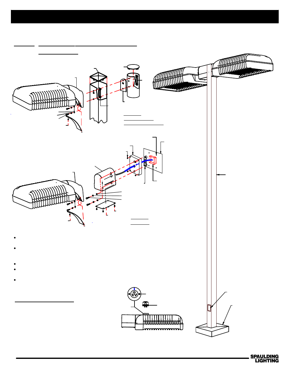
CIMARRON LED
(LUMINAIRE)
STRAIGHT
SQUARE POLE
(SHOWN)
HAND HOLE
BASE COVER
SHIPPED WITH POLE
HARDWARE KIT
TEMPLATE
DRILL
(4 HOLES)
CAST PLATE
HOLE PLUG
NUTPLATE
WALL
JUNCTION BOX
STRAIGHT
ARM
SCREW
COVER
FLAT WASHER
HEX BOLT
LOCKWASHER
SCREW
CURVED
ARM
CURVED ARM
MOUNT
FIGURE
3
COVER
SCREW
CAST ARM
POLE COVER
POLE
COVER
CAST ADPTOR
NUT PLATE
FLAT WASHER
HEX BOLT
LOCKWASHER
SQUARE AND
ROUND POLES
NORTH
PHOTOCONTROL
SCREW
RECEPTACLE
WALL
MOUNT
FIGURE
4
268-1300-9901 CIMARRON INSTALLATION INSTRUCTIONS (PG 2/3)
SAVE THESE INSTRUCTIONS
701 Millennium Boulevard Greenville, SC 29607 (864) 678-1000
www.spaulding-ltg.com
93034033 CIMARRON CL1 LED INSTALLATION INSTRUCTIONS (PG 2/2)
4. MOUNTING FIXTURE WITH CURVED ARM
Use same procedure as shown on Page 1,
except Arm Cover has (1) Screw.
5.
MOUNTING FIXTURE WITH WALL PLATE
Using template, locate holes in bracket around junction
box on the wall. Mark hole locations. (See Fig. 4)
Drill wall for the hardware appropriate for the type wall.
Use 1/4 diameter bolt (supplied by others) and attach
Wall Plate to Wall with Nut Plate inside.
Pull the supply wires from junction box through Plate.
Apply caulking sealant (supplied by others) around the top
and two sides of the bracket where it meets the wall.
Follow same Instructions as Steps 1, 2, 3 and 4.
PHOTOCONTROL OPTION
NOTE: THE LIGHT WILL NOT OPERATE
WITHOUT A PHOTOCONTROL SWITCH OR A
SHORTING CAP IN PLACE. DO NOT LEAVE
RECEPTABLE OPEN TO THE ELEMENTS.