Driven by safety – Simpson Hybrid User Manual
Page 7
DRIVEN BY SAFETY TEAMSIMPSON.COM 13
DRIVEN BY SAFETY
VISIT
TEAMSIMPSON.COM
TO SEE THE
FULL LINE OF HEAD AND NECK RESTRAINTS
OR
CALL
800.654.7223
With the 2012 mandates in effect, the Simpson Hybrid Pro has endured stringent testing to
prove that it is the safest option on the market. As part of Simpson’s SFI 38.1 certifi ed line of
Head and Neck Restraints, it was designed with the lowest profi le for maximum comfort and
maneuverability. Expertly engineered by Trevor Ashline with Safety Solutions technology,
it provides the quickest entry and exit from the race car and is NASCAR approved. From the fi rst hit to the
last, the Hybrid Pro gives you every advantage.
12 TEAMSIMPSON.COM TOLL FREE 800.654.7223
OPTIONAL
SEA
T BEL
T ANCHOR S
YS
TEM
OPTIONAL
HYBRID MOLDED P
AD
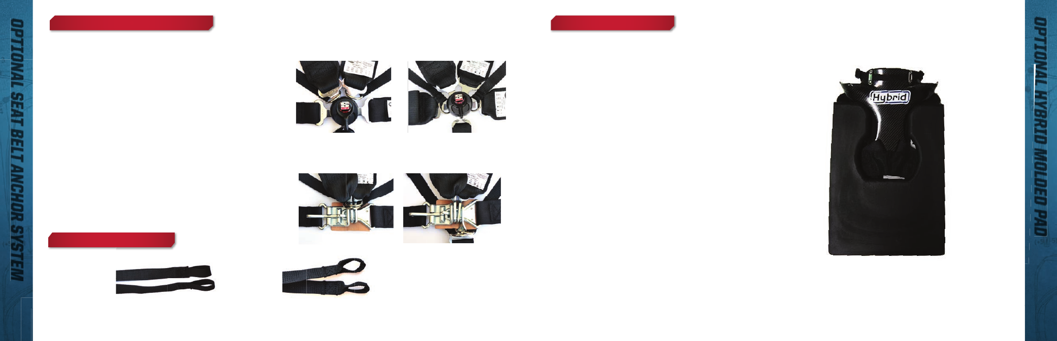
The Hybrid Optional Molded Pad is placed
behind the driver between the seat and the
driver’s back and shoulders.
The U-Shaped Molded Pad can be cut, and/or
trimmed to fi t driver’s seat. Tape, glue, or Velcro
the molded pad in place depending on type of
seat. If the seat has a cover, the pad can be
installed under the cover.
The Pad is inserted into the seat back. When
the driver sits back, the device nests into the
voided area creating one smooth surface behind
the driver’s back. The wings of the restraint
should extend under the shoulder belts between
the seat back and the driver.
The SAS straps need to attach to the seat belt buckle; the
SAS is an additional load path for the restraint allowing for
stabilization of the driver.
Camlock Attachment Slide each SAS O-ring onto two of
the camlock buckle tongues.
See Figure 18
Latch-in-Link Attachment Pair the SAS O-rings and slide
them into the latch link shoulder belts or the fi ve point
depending on your set-up.
See Figure 19
The SAS straps should be adjusted to be snug when the
buckle is latched with no more than 2 fi ngers of room.
Adjustment is made by sliding the 1” webbing attached to
the loops through the 3-bar adjuster.
OPTIONAL HYBRID MOLDED PAD
OPTIONAL SEAT BELT ANCHOR SYSTEM (SAS)
OPTIONAL SAS LOOPS AVAILABLE
Figure 18
Figure 19
Figure 20
Figure 21
Figure 22