Schwank STR-CANADA User Manual
Page 12
SP-MSTR-AC-11A
STR Manual
RD: NOV, 2003
RL: 11
KH
Page 8
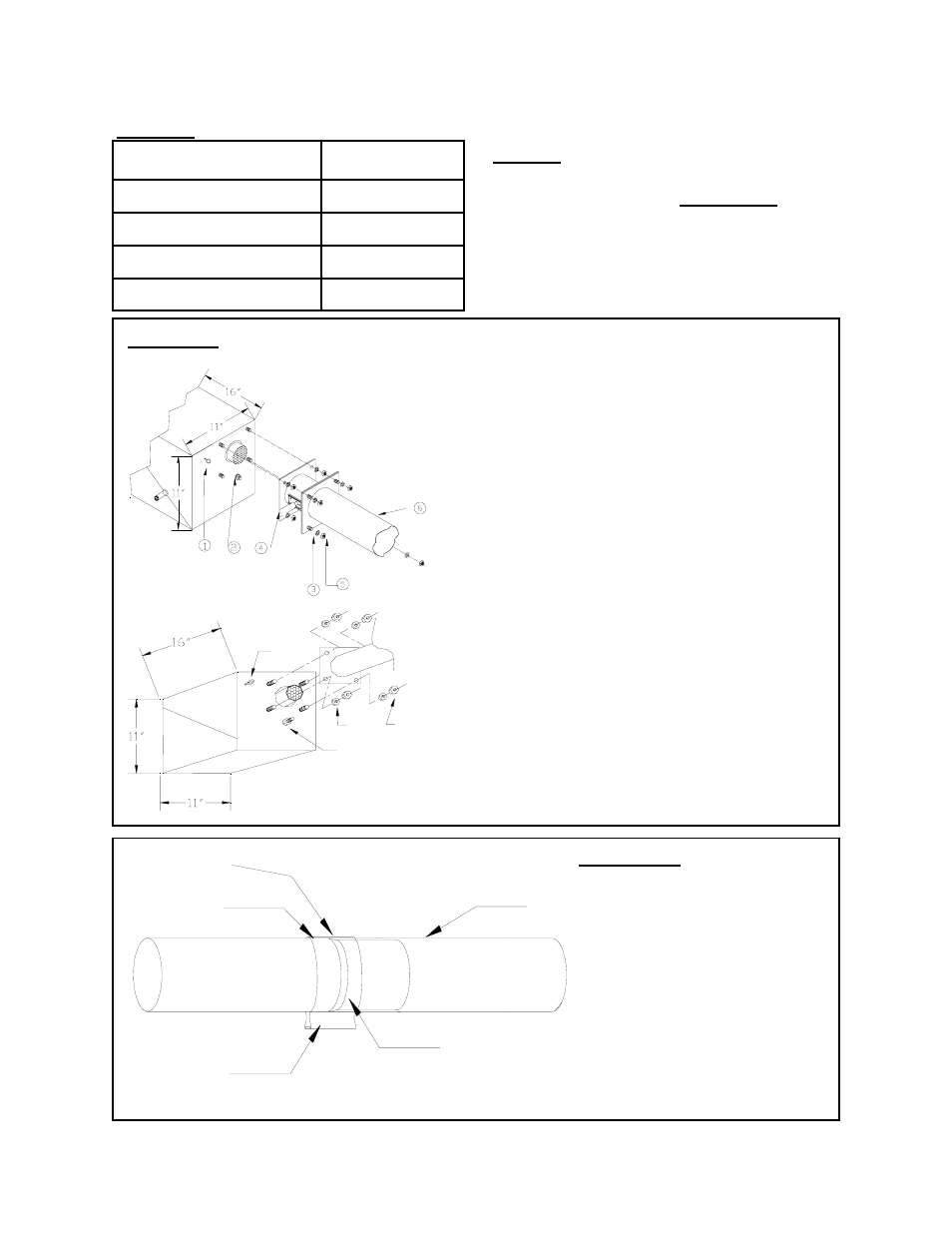
FIGURE 9 BOLTING BURNER TO FLANGED TUBE
1 Tube
2 Tube Coupler
3 Swaged section of tube.
4 Point at which the Swaged
tube slides into another section
of tube.
5 Once the two tubes are joined,
place centre of the coupling
over the line of the joint and
tighten.
TABLE 4
MODEL
TURBULATOR
LENGTH
STR 60-30
14’ 0”
STR 60-20
14’ 0”
STR 45-20
5’ 0”
STR 45-10
5’ 0”
NOTE: Where required, the STR Series
Heaters will be supplied with turbulators,
factory installed into the end tube (s) of the
system configuration.
FIGURE 10 COUPLER KIT
1 Eye Hook
2 Fifth Nut (Holding Inner Burner to
Housing) Do not loosen or Remove.
3 Lock Washers x 4
4 Burner Flange Adapter
5 Nuts x 4 {Nuts could be shipped c/w
lock washers as one piece}.
6 Flanged Section of Heating Tube
•
Align the four burner bolts through
the tube flange, secure tightly with
lock washers and nuts
•
Note: A Flange Gasket is not re-
quired for this application.
•
Secure suspension chain to eye hook
in order to stabilize burner.
3
2
1
4
5
1
2
3
4
STR-45 models
STR-60 Models