Minimum, Iep 1524, Heater mounting – Schwank IEP-1524 User Manual
Page 10
10
IM110810
RD: AUGUST 2011
RL; 1A
BA
InfraSave IEP-1524 Manual
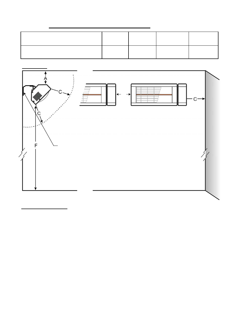
TABLE 2:
MINIMUM
REQUIRED CLEARANCES
IEP 1524
Above ‘A’
Inches [cm]
Floor ‘F’
Inches [cm]
Clearance ‘C’
Inches [cm]
1500 W, 115 - 120V, 60 Hz, 13 Amps
12” [30]
72” [180]
36” [90]
Spacing ‘D’
Inches [cm]
More than
36” [90]
Heater Mounting:
1. Mount the heater on a non-combustible surface or structural member, and maintain at
least all minimum clearances indicated in Table 2 and Figure 2 above.
2. Use the Mounting Bracket supplied with the heater - see Figure 3 next page.
3. Hardware to fasten the Mounting Bracket to the structure is field supplied by the installer
since the type of hardware fastening is determined by site conditions.
4. Connect heater to a 115 - 120 Vac, 60Hz, 13 Amp copper wire circuit that is properly
grounded. Electrical connection must be performed by a qualified electrical tradesperson.
Installation must conform with the latest edition Electrical Code ANSI/NFPA N0 70 in the
U.S.A. and PART 1 CSA C22.1 in Canada.
5. Never allow an electrical cord to pass in front of the heater or to come into contact with
any hot surface of the heater.
LONG AXIS: HORIZONTAL
UP TO
45°
FIGURE 2: MINIMUM Required Clearances
MOUNT BRACKET TO STRUCTURAL MEMBER OF A
NON-COMBUSTIBLE WALL / SURFACE
DO NOT PLACE ANYTHING CLOSER THAN 3 ft (90 cm)
(CLEARANCE ‘C’) IN FRONT OF OR BELOW THE HEATER
continued ...
D