Schwank Parasol Series Post Mount 24 volt User Manual
Page 25
4BN/L6-24,4SN/L5 -24 Manual
IM100310
RD: MAR, 2010
RL: 1A - BA
25
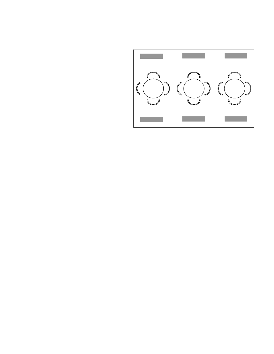
Sample Patio Set-up
:
Dining patio with 3 zones. Each zone has 2 opposing heaters that provide best comfort when op-
erating simultaneously as a pair. The entire patio area will be controlled by one Hand Set Trans-
mitter.
Set all ‘House Codes’ to the same Letter Code
on one Hand Set Transmitter and six receivers
(one in each heater). Heaters H-1 & H-2: Set
receiver Unit Codes to “1” - the hand set trans-
mitter will activate both heaters in Zone 1 with
Group I / Button 1
.
Similarly, set receivers in heaters H-3 & H-4 to
“2” and H-5 & H-6 to “3”. Both Zone 2 heaters
turn On/Off with button set “2” and both heat-
ers in Zone 3 with button set “3”.
Alternately, for individual control of heaters,
set each receiver Unit Code to a unique number (H-1 to “1”, H-2 to “2”, etc.). Heaters H-1 to H-4
will be controlled by hand set transmitter Group I - Buttons 1 to 4 and heaters H-5 and H-6 will
be controlled by Group 2 - Buttons 1 and 2.
Kits / Part Numbers for Remote Control systems:
NOTE: Items are ordered separately
JP-1234-RK
REMOTE CONTROL RECEIVER –
Typically Factory Installed - order as optional accessory
Can be ordered as a field installed Kit; Includes: receiver, wires, Velcro Fastener,
instructions
JP-1234-HS
REMOTE CONTROL HAND SET – Accessory; single item with Velcro fas-
tener
Refer to the wiring diagram Section 14.1, Page 18.
All wiring should be done by a qualified electrician. The heater, when installed, must be electri-
cally grounded in accordance with local codes or, in the absence of local codes with the National
Electrical Code, ANSI/NFPA 70, or the Canadian Electrical Code, CSA C22.1. All wiring and elec-
trical connection must conform to the requirements of the above codes. See Section 10, page 14.
NOTE: the ON/OFF switch may be removed from the heater for secure control of the heater using
the remote control hand set only. A rubber insert is supplied with the heater to fill the hole in the
control cover where the switch was mounted.
1
2
3
H-1
H-2
H-3 H-5
H-4 H-6
ZONE
1
ZONE
2
ZONE
3