Warning – S&S Cycle IST Ignition System for 2004-Up Harley-Davidson Models User Manual
Page 3
2
3
This is a supplement to instruction 51-1136. The 51-1136 sheet details installation on 1999-’03 motorcycles equipped with Harley-
Davidson® Twin Cam 88® engines. If you did not receive that sheet in your packaging, please visit the S&S® website, www.sscycle.com to
download a copy. You can contact the S&S Tech Department to get a copy by calling (608) 627-8324.
6- Starting from this point, route the Cylinder Head Temperature sensor wiring harness to the sensor. Make sure it does not contact any moving or
hot parts. Use wire-ties to secure the harness along its routing.
7- Next, route the Knock Sensor wiring harness in the same way. Be sure to use wire-ties to secure the harness along its routing.
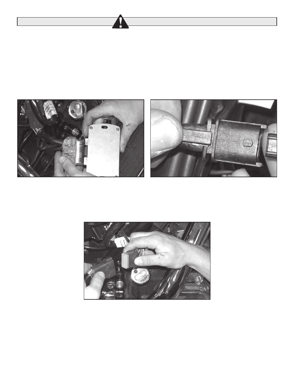
8- Connect the 32-Pin connector to the module as shown in Picture 5, below left. Listen for an audible click to confirm the connection. Next, with
wiring harness run to the sensors, connect the Knock and Cylinder Head Temperature sensors as illustrated in Picture 6, below right. Again,
listen for an audible click when they connect.
9- Now connect the 12-pin connector from the IST harness to the stock Harley-Davidson® harness as shown in Picture 7, below.
10- Use the included spacers as necessary and install IST module in place of the O.E. unit. See below for specific model instructions.
A- Boggers
1- You will need to use two (2) 0.200" spacers (included in the IST hardware kit) between the module and its mounting position to allow
clearance for the 32-pin Packard connector.
B- Softail® models
1- You will need to use two (2) 0.200" spacers (included in IST hardware kit) between the module and its mounting position to allow clearance
for the 32-pin Packard connector.
C- Dyna™
1- The webbing on the electrical caddy interferes with the IST module. The hardware and a bracket to offset the mounting position are
included in the installation kit and are detailed in Picture 8 on the next page.
2- Be sure to connect the 32-pin Packard connector to the module before you install it in the electrical caddy.
3- Picture 9 (next page) illustrates how to mount the module in the electrical caddy.
WARNING
Picture 5
Picture 6
Picture 7