Warning caution caution – S&S Cycle Clearancing S&S Billet Rocker Covers for Harley-Davidson Rocker Arms User Manual
Page 2
S&S
®
has experienced minor clearance problems when installing
some Harley-Davidson
®
rocker arms in S&S Billet Rocker Covers.
The following procedures should be performed in addition to
those described in S&S Rocker Cover Instructions No. 00-3855.
1.
Before placing rocker covers on engine, install
rocker/shaft/support assemblies in lower rocker cover as
described in Instructions No. 00-3855. Secure supports to
lower rocker housings by placing 4 each 5/16-18 nuts (not
provided) on protruding ends of 5/16” bolts and
tightening to 15 ft-lbs.
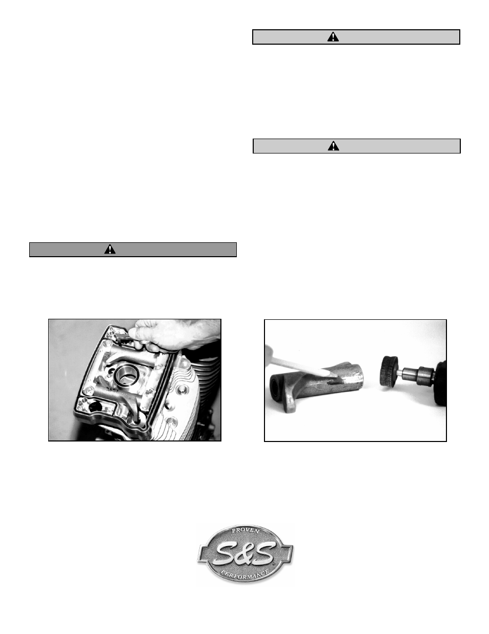
2. Slowly rotate rocker arms through full range of motion and
observe for interference between rocker arms and lower
rocker cover. Use feeler gauge to measure distance between
rocker arm and rocker cover at closest point. See Picture 1.
Minimum acceptable clearance is .025”.
3.
If clearance is less than .025”, remove rocker arm from rocker
cover and carefully file or grind rocker arm to obtain correct
clearance. Remove least amount of material required to
obtain correct clearance. See Picture 2.
Metal particles are potentially hazardous, especially to hands
and eyes. Always wear protective clothing such as goggles
and gloves when working with metal. When using
compressed air, always direct air stream away from yourself
and others nearby.
S&S recommends clearancing rocker arm rather than lower
rocker housing. However, removing excessive material from
rocker arm may weaken it, resulting in failure and engine
damage. In most instances, only a few thousandths of an inch
of metal must be removed to provide adequate clearance.
4. Remove burrs and rough edges of relieved area with fine file
or polishing wheel on hand-held grinder. Clean rocker arm
thoroughly with solvent and dry with compressed air.
Failure to remove burrs and metal chips may result in engine
damage not covered under warranty.
5. Reinstall rocker arm and confirm correct clearance.
6. Proceed with installation according to instructions No. 00-3885.
2
WARNING
CAUTION
CAUTION
Picture 1
Picture 2
Because every industry has a leader