Top view cam side drive side – S&S Cycle Piston and Big Bore Kits 98 and 107 for 1999-06 and 2007-14 Big Twins User Manual
Page 4
4. Piston Installation
NOTES
• Pistons are identical and can be installed in either cylinder.
• CAUTION: THE PISTONS MUST BE ORIENTED SO THAT THE VALVE
RELIEFS MATCH THE CORRESPONDING VALVES. THE INTAKE
VALVE RELIEF IS LARGER THAN THE EXHAUST VALVE RELIEF.
THE 107" PISTONS HAVE A NOTCH ON THE BOTTOM OF THE
SKIRT, THIS NOTCH MUST BE INSTALLED TOWARD THE CENTER
OF THE ENGINE. THE 98" PISTONS DO NOT HAVE A NOTCH AND
MUST BE INSTALLED WITH THE VALVE RELIEFS ORIENTED TO THE
APPROPRIATE VALVE.
• Check piston pin to connecting rod bushing clearance. Clearance
should be between 0.0007" and 0.0012". Bushing should be replaced
if clearance exceeds 0.002".
a. Place rubber tubing over the cylinder studs to prevent damage to
the pistons and rings during assembly.
b. Place a clean sheet of plastic over the crankcase openings to
prevent anything from dropping into the crankcase.
c. Install one of the piston pin clips into each of the pistons according
to the instructions included in the piston kit.
d. Lightly oil the piston pin, piston pin bore and upper connecting rod
bushing with clean 20W-50 oil or assembly lube.
e. Hold the piston over the connecting rod with the piston facing the
correct direction and the piston pin bore and upper bushing bores
lined up.
f. Install the piston pin through the piston pin bore and through the
connecting rod bushing until the pin contacts the clip.
g. Install the other piston clip. Ensure that both clips are fully seated.
h. Repeat procedure for the rear piston.
5. Cylinder Installation
a. Bring the front cylinder to TDC.
b. Apply a light coating of oil to the piston and rings.
c. Lightly oil the new cylinder base o-ring and install on the cylinder.
d. Lightly oil the new o-rings for the lower cylinder deck alignment
dowels and install.
e. Verify that the ring gaps are orientated correctly, refer to Picture 5a.
f. Remove the rubber tubing from the cylinder studs.
g. Compress ring pack by using a suitable ring compressor. If possible,
position the ring compressor so that you can see the oil expander
gap during installation. Picture 5b.
h. Install cylinder on piston, making sure not to overlap oil ring
expander.
i. Remove ring compressor.
j. Remove plastic sheeting covering crankcase.
k. Slide the cylinder down until it seats against the crankcase.
l. Rotate the engine until the rear cylinder is at TDC.
m. Repeat procedure for the rear cylinder.
6. Cylinder Head Installation
Head Gasket Tightening Torque Specifications
Multi layer steel (MLS) head gasket, PN 106-3714, 0.045" thick or PN 900-
0216, 0.030" thick
a. Check surfaces for flatness and imperfections, an excessively rough
finish may cause gasket failure.
b. Check all hardware for defects. Clean all threads and lubricate with
clean oil. Lubricate the underside flange of the head bolts with
clean oil (wipe away excess).
c. The head bolts are two different lengths. The short ones go on the
spark plug side; the long ones go on the pushrod side.
d. Place the head gasket on the cylinder and locate the gasket using
the cylinder head alignment dowels. Either face of the gasket can
be up, there is not a specific top or bottom to the gasket.
NOTE: Do not use the cylinder head alignment dowel O-rings with MLS
head gasket.
e. Once the gasket is in place, make sure that it fits the bore. The
gasket should not hang into the bore or combustion chamber area.
f. If using cylinder heads other than stock, check the brass rivets
of the MLS gaskets to ensure the rivets do not interfere with the
sealing surface in any way.
g. Important! In order to properly seal the head gasket, the head
bolts must be torqued in the sequence shown in the next step,
fully loosened, then torqued again a 2
nd
time. Follow the head
tightening sequence in the next step then fully loosing the head
bolts ¼ turn at a time in the sequence shown in Picture 6 until fully
loose. Repeat the tightening sequence in step h below, a second
time.
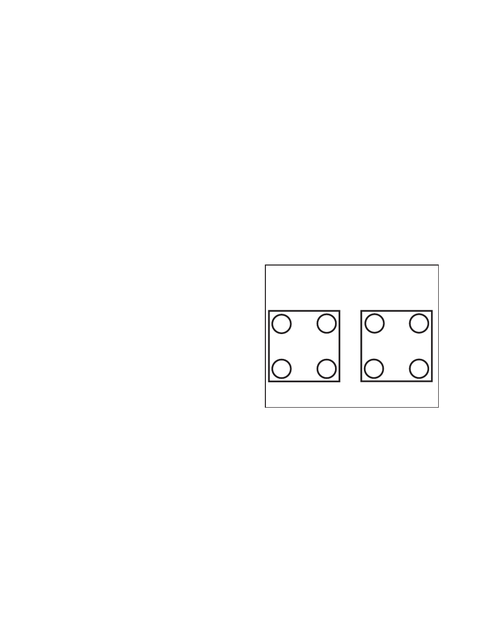
h. Tighten the head bolts according to the following procedure, start
with the front head then the rear head.
i. Tighten each bolt finger tight using the sequence in Picture 6.
ii. Tighten each bolt to 10-12 ft-lbs using the sequence.
iii. Tighten to 15-17 ft-lbs using the sequence.
iv. Finally, tighten the bolts an additional ¼ turn (90˚).
3
4
2
1
4
3
1
2
Top View
Cam Side
Drive Side
Front Cylinder
Rear Cylinder
7. Final Assembly
Assemble the remaining items according to the Harley-Davidson
service manual specific for your motorcycle.
8. Tuning
S&S big bore kits increase the displacement and compression ratio of
your engine. The fuel and ignition systems must be calibrated for these
changes before the engine is driven and break-in is attempted. It is
recommended that a performance carburetor such as the S&S Super E
or G be used with the correct jetting for the engine size for carbureted
models. Fuel injected engines must be tuned using a replacement
ECU such as the S&S VFI module, or an aftermarket tuner such as the
DynoJet® Power Vision® tuner.
NOTE: The S&S VFI module is not compatible with 2008–up Touring
models with electronic throttle control. S&S recommends the Dynojet®
Power Vision® tuner for these applications.
4
Picture 6