S&S Cycle 650 Sidewinder Valve Spring Kits for X-Wedge Engines User Manual
Page 3
3
F. Measure distance between top collar keepers and top of valve
guide seal. See Figure 2, Dimension B. Distance must be at
least .060" greater than the valve lift of the cam to be used.
G. Repeat steps A-F for remaining valves and record all
measurements in the table below. Be sure to keep track of
all parts during assembly to assure they are installed in the
same location and with the same valve clearances they were
measured with.
4. Adjust the installed spring heights with the provided shims so
that each spring meets the following dimensions.
Note: If shims are used, they are to be placed under the integral
seal.
.585 Sidewinder Springs: 1.970 +/- 0.010"
.650 Sidewinder Springs: 2.000 +/- 0.010"
Note: Installed spring height is the distance between spring contact
surfaces of top and bottom collar when the valve is closed.
5. Install valves, shims (if necessary), valve seals and valve springs
in heads. Install all S&S springs with smaller O.D. toward top
collar. Be sure valve guide seals are in place. Install top collars
and keepers.
Note: Installed height should be the same for each spring assembly, ±
.010".
6. Install the cylinder heads. When the remaining valve train
components are assembled, rotate the engine a few times to
ensure there is no binding in the valve train.
CAUTION
• Installing springs at height less than recommended dimension
will cause rapid spring fatigue resulting in possible engine
damage.
• Installing springs at height above recommended dimension will
decrease spring tension resulting in possible valve float and
engine damage.
• Failure to establish required clearances may cause valve seal
failure and other, more extensive engine damage not covered
under warranty.
WARNING
Valve spring assembly is under considerable tension when
compressed and is potentially dangerous. Wear eye protection
and take due caution when checking for coil bind and during
installation. After assembly, carefully strike tip of valve stem
with plastic hammer to insure that keepers are seated. Direct
spring assembly away from face and body during this procedure.
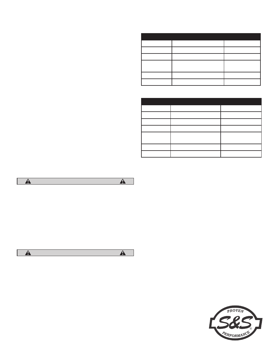
Replacement Parts
Part Number
Item
Quantity
90-2094-S
Valve Keeper
8
106-0739
.585" Valve Spring
4
90-2070
Top Valve Spring Collar
4
90-2281
Bottom Valve Spring Collar
with Seal
4
90-2086
Shim
4
90-2087
Shim
4
.585 Sidewinder Valve Spring Kit 106-0772
Part Number
Item
Quantity
90-2094-S
Valve Keeper
8
106-5689
.650" Valve Spring
4
106-5690
Top Valve Spring Collar
4
106-3827
Bottom Valve Spring Collar 4
90-2281
Bottom Valve Spring Collar
with Seal
4
500-0013
Shim
4
500-0014
Shim
4
.650 Sidewinder Valve Spring Kit 900-0212