S&S Cycle 590 Lift Valve Spring Kits 90-2060 and 90-2063 for 1948–1984 Big Twin Engines User Manual
Page 4
• Installing springs at height less than recommended dimension will cause rapid spring fatigue resulting in possible engine damage.
Engine should be frequently disassembled for spring tension measurement if springs are shimmed past recommended dimension.
• Installing springs at height above recommended dimension will decrease spring tension resulting in possible valve float and engine
damage.
• Failure to establish required clearances may cause valve seal failure and other, more extensive engine damage not covered under
warranty.
Valve spring assembly is under considerable tension when compressed and is potentially dangerous. Wear eye protection and take
due caution when checking for coil bind and during installation. After assembly, carefully strike tip of valve stem with soft hammer to
insure that keepers are seated. Direct spring assembly away from face and body during this procedure.
4. If S&S valve spring kits 90-2060 and 90-2063 are installed according to instructions and specifications in this manual, cams with valve lifts of
up to .590” may safely be used without coil bind. However, if you wish to check for coil bind, here is the procedure. This must be done for
each spring individually. Observing previous warning, check for coil bind as follows:
A. Assemble one spring with top and bottom collars, and place in vise or spring checking device and carefully compress to length equal to
installed height minus valve lift minus .060". Using .590" lift cam with springs installed at 1.480", for example, compress spring to 1.480"
- .590" - .060", or .830". Confirm that spring can compress to at least this dimension without adjacent coils making contact (binding). If
clearance between coils is insufficient, a different spring pack or cam with less lift must be used.
B. Repeat procedure for all remaining springs individually.
5. Lubricate valve stem with thin coat of assembly lube and install valve. Install lower collar, valve guide seal if applicable, then valve springs and
top collar. Install all S&S® outer springs with O.D. chamfer toward top collar.
6. Check clearance between rocker housing and top collar. At same time confirm clearance between top collar and rocker arm.
A. Coat areas of rocker housing surrounding spring retainer with machinist’s blue.
B. Place coat of putty approximately .060" thick on top of top collar, avoiding valve stem.
C. Carefully install rocker housings on heads and install head and pushrod assemblies on engine. Adjust pushrods according to manufacturer’s
instructions. If hydraulic lifters are used, lifter must be completely collapsed to check clearances, and pushrods adjusted to zero lash. For
final installation pushrods will be adjusted according to manufacturer’s instructions.
D. Rotate flywheels four complete revolutions in normal direction of travel. If resistance is encountered, disassemble engine and determine
cause before proceeding.
E. Remove heads and carefully remove rocker housings from heads. Inspect machinist’s dye and clay for evidence of contact. If rocker has
contacted clay, thickness of clay beneath indentation should be at least .045".
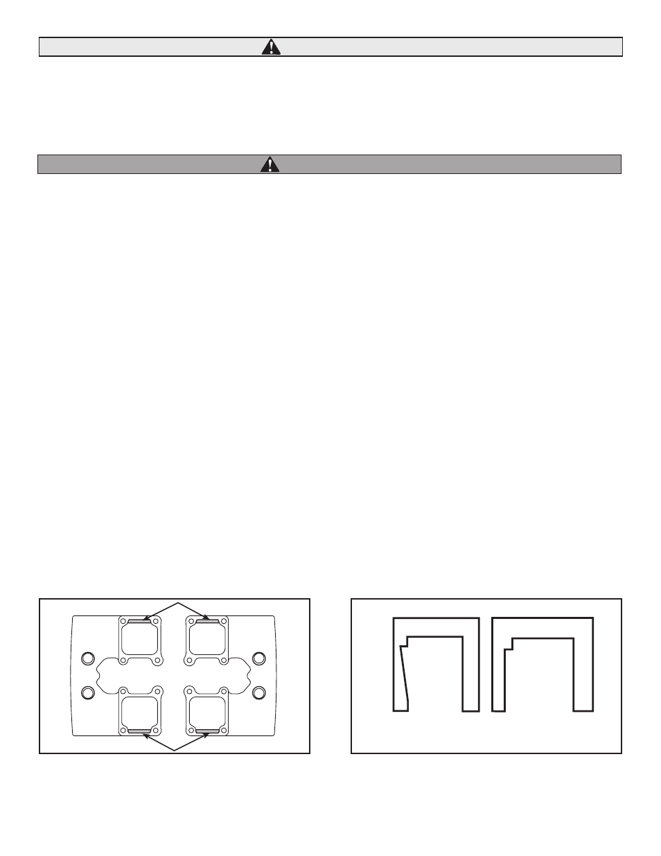
F. Carefully remove metal from rocker housing or rocker arm to obtain .060" clearance. See Figures B & C. Spring and collars should not be
modified in any fashion.
4
CAUTION
WARNING
Figure B: Lines indicate areas most likely to require
modification for spring retainer clearance. Relief should be
cut at an angle, not vertical.
Figure C: Valve compartment of rocker housing (cross
section). If required, relief should be cut at an angle
approximately the same as angle of valve travel, not vertical.
Remove least amount of material as possible to obtain proper
clearance.
Correct
Incorrect