Caution – S&S Cycle Spring Kit 90-2053 (Fits all Panhead and Shovelhead Engines) User Manual
Page 2
The components of this kit are designed to be used together and
must not be mated with stock springs or retainers or springs or
retainers of another brand. The reasons are:
1.
S&S
®
springs are wound in a different direction than stock
springs.
2.
S&S inner springs are larger in diameter and longer than
stock springs.
3.
S&S outer springs are longer than stock springs.
4.
S&S aluminum top retainers are designed to correctly
accommodate the larger diameter of the inner springs and
longer length of both S&S springs.
INSTALLATION INSTRUCTIONS
1.
Assemble one valve at a time using stock bottom retainer,
valve guide seal (if equipped with seal), S&S aluminum top
retainer and stock Harley-Davidson
®
keepers as shown in
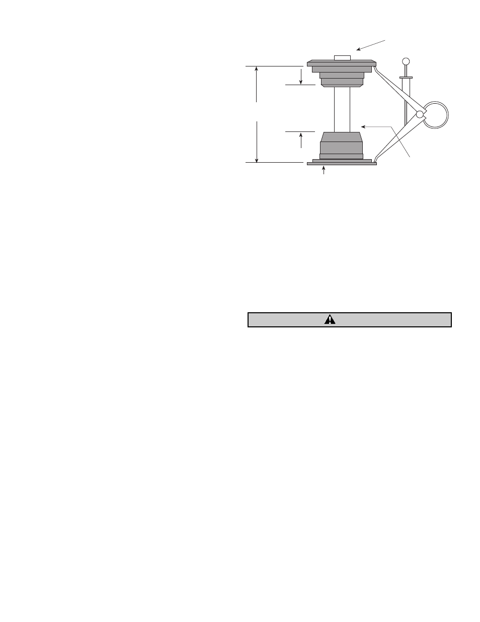
Figure 1. Tap valve stem with soft hammer at top retainer
to seat stem and keepers.
2.
While pulling up on top retainer to hold valve closed, take
measurements A and B and record them. Perform this step
for each valve. Identify and separate collars and valves so
they can be installed in same position from which you took
measurements. On late heads with valve guide stem seals,
take measurement B to top edge of seal.
3.
Measurement A will normally fall in range shown in Figure
1. This range will provide enough clearance to run cams
with lifts as high as .550".
A.
If measurement A is less than 1.490" Material must be
removed from underside of bottom spring retainer
either from shoulder where retainer contacts guide or
from flat where retainer contacts head. Up to .050" can
be removed from retainer where it contacts shoulder of
guide. If material is removed from this area, retainer
must be installed on guide and checked for contact
between flat of retainer and head. On these installations
retainer must not contact head. Grind head at points of
contact to obtain clearance. On installations where
retainer rests on head instead of guide, up to .050" can
be surface ground from flat of retainer to gain necessary
clearance. Cam installations with lifts greater than .550"
require measurement A to equal 1.505" plus cam lift
minus .550". Example: Cam to be used has lift of .575".
Measurement A = 1.505" + .575" - .550" or 1.530". Basic
rule of thumb - Measurement A must equal length of
coil bound spring + cam lift + .020" minimum.
B.
If measurement A is more than 1.520" - Shims may be
fabricated and placed between guide shoulder and
retainer or retainer and head. Shimming is
recommended particularly in racing applications. On
most street engines where higher rpm usage is limited
shimming is left to discretion of builder.
4.
Measurement B will normally be less than .600" to .620"
shown in Figure 1.
This range will provide enough
clearance to run cams with lifts as high as .550". Subtract
measurement B recorded earlier from .610" for each valve
and grind tops of valve guides. Remove only the difference
in measurements. Carefully remove burr on inside diameter
of guides before installing valves so as not to scratch valve
stems. Just barely break corners on outside diameters of
exhaust guides. Contour outside diameters of intake guides
in engines equipped with valve guide seals to original
shapes. Cam installations with lifts greater than .550"
require measurement B to equal cam lift plus .050" to .070".
Example: Cam to be used has lift of .575". Measurement B =
.575" + (.050" to .070") or .625" to .645".
5.
Perform steps 1 and 2 again and compare measurements with
ones previously recorded. Cams with lifts as high as .550" may
be used when A is 1.490" to 1.520" and B is .600" to .620".
NOTE: Valves sunk deep in seats cause rocker arms to contact valve
stems at a different angle. In extreme instances edge of rocker
arm may contact outside edge of top valve spring retainer at valve
closed position. This causes top retainer to rock which may result
in collar failure. If there is any doubt whether contact exists, we
recommend that rocker arm to retainer clearance be checked.
Improper clearance between moving parts may cause contact
and damage or destruction of parts. Failure of one or more
parts can produce abrasive contaminants which may circulate
in the engine oil causing damage to other engine components.
6.
To check for contact between rocker arm and top spring
retainer, perform the following steps:
A.
Paint outside edge of top collar with machinist's blue
and install heads on engine. Modeling clay may also
be used.
B.
Install rocker boxes and pushrods and rotate engine
four revolutions in normal direction of travel.
C.
Remove rocker boxes and examine collar edges for
evidence of any contact with rocker arm.
D.
If contact occurs, remove minimum material necessary
from rocker arm at point of contact.
NOTES:
●
On 1983 and '84 shovelhead engines, rocker cover casting to
top retainer clearance is reduced. When installing S&S
Spring Kit 90-2053 on these engines, be sure to check this
clearance and remove material from rocker cover to assure
.060 minimum clearance.
●
S&S Spring Kit 90-2053 was designed primarily for Harley-
Davidson
®
shovelhead engine. If kit is installed in Harley-
Davidson
®
panhead, valve cover modification will be needed
to provide sufficient clearance between top retainer and
rocker cover. We recommend 1/8" minimum clearance. In
most cases this can be accomplished by peening cover in area
of contact with ballpeen hammer.
2
Before taking measurement, tap
valve stems to set keepers.
Grind material from
top of guide to obtain
measurement B.
A
1.490"
1.520"
B
.600"
.620"
Remove material or shim between bottom of retainer
shoulders and guides or retainer flats and head to obtain
measurement A.
Figure 1
CAUTION