Caution – S&S Cycle Pushrod Kits and Travel Limiters (all) User Manual
Page 7
10. Repeat above procedures for rear cylinder.
11. Replace sparkplugs and pushrod tube clips. Start
motorcycle and check for leaks.
E.
S&S
®
hydraulic lifter limited travel kit (HL
2
T)
All reference to Harley-Davidson
®
part numbers is for
identification purposes only. We in no way are implying that any
of S&S
®
Cycle’s products are original equipment parts or that they
are equivalent to the corresponding Harley-Davidson
®
part
number shown.
NOTES:
●
The S&S HL
2
T kit is designed to limit the travel of the
hydraulic lifter making it impossible for the lifter to
collapse. Stronger valve springs are often used to avoid
valve float at high rpm. The HL
2
T kit prevents high valve
spring pressure from collapsing lifters. With the HL
2
T kit
installed, stock hydraulic lifters work like solid lifters at high
rpm, while retaining normal hydraulic function for minimal
noise and maintenance under normal conditions. Another
advantage of the HL
2
T kit is that if a valve is held open
when the engine is not running, valve spring pressure will
not cause lifters to bleed down and collapse. Collapsed
lifters can cause hard starting and excessive valve train noise
when engine is restarted. Adjustable pushrods must be used
with the HL
2
T kit.
●
S&S Kit 33-5338 for 1984 & 1985 big twin, have smaller
diameter hydraulic plunger bodies which measure about
.612". S&S Kit 33-5339 for 1986 to present big twins, have
larger diameter hydraulic plunger bodies which measure
about .655". An early S&S kit must not be used in a late set
of tappets. Installation procedure is the same for either kit.
●
The earlier Harley-Davidson
®
Twin Cam 88
®
lifters, Harley-
Davidson
®
part numbers 18538-99 & 99A, require the S&S
HL
2
T kit number 33-5339. The later Twin Cam 88
®
lifters,
Harley-Davidson
®
part number 18538-99B, require the S&S
HL
2
T kit number 33-5338. Both kits are included with the
Sidewinder
®
engine kits, and either kit is installed and
adjusted the same way – remove the retaining clip from the
top of the lifter, and remove the piston assembly and spring
from lifter body. Place the appropriate HL
2
T travel limiter into
the bore of the lifter and replace removed components in the
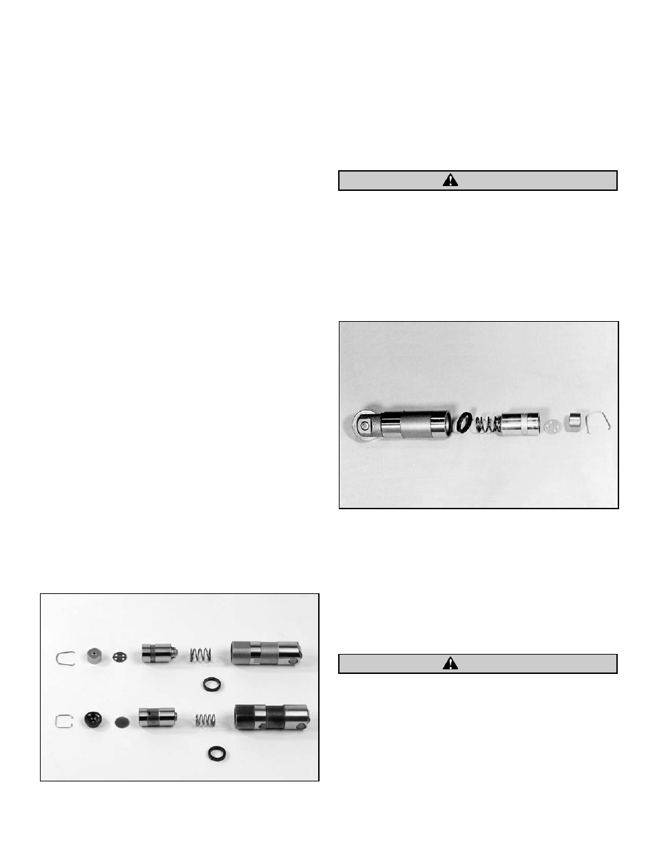
order that they were removed. See Picture 1.
INSTALLATION
1.
Remove tappet assemblies from engine being sure that
each one is kept with its original tappet block.
NOTE: This procedure is the preferred method of installation.
However, kit can be installed without removing lifters from engine.
2.
Remove hydraulic piston retaining wire clip from one
assembly at a time.
Be careful not to bend wire clip during disassembly.
3.
Completely disassemble tappet removing all parts.
4.
Thoroughly clean all parts including tappet body.
Remove any oil which might prevent hydraulic unit from
fully collapsing during adjustment.
5.
Insert one spacer from S&S HL
2
T kit in tappet body.
6.
Reassemble tappet in reverse order making sure original
parts are returned to their original positions. See Picture 2.
7.
Replace wire retaining clip in tappet body.
8.
Put tappet back in original tappet block.
9.
Repeat Steps 2 through 8 for three remaining tappets.
10. Reassemble engine with modified tappets.
11. Adjust pushrods.
NOTE: In all cases engine must be cold and lifter must be at
lowest point of travel for pushrod adjustment
To prevent accidents, remove ground cable from battery.
7
CAUTION
Picture 1
Picture 2
CAUTION