Caution – S&S Cycle Transmission Case, 4-to-5 Speed User Manual
Page 4
5.
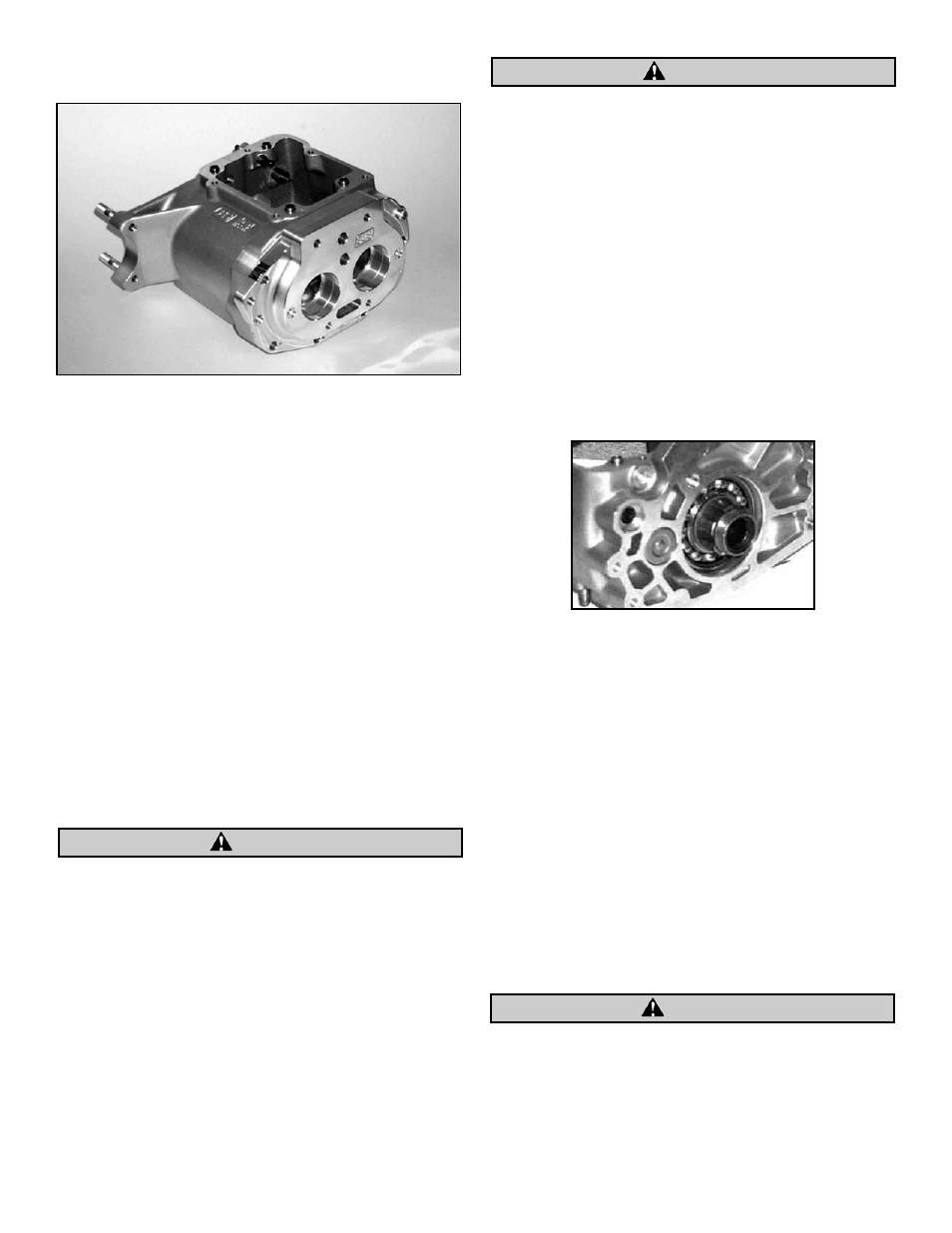
Clearance access door to match clearance cut in 56-1051
transmission case below starter motor area. See Picture 3.
B.
Parts Preparation
1.
Countershaft
Remove approximately 0.280 in. from non-threaded
end of countershaft and remove burrs. Correct length of
modified countershaft is 7.830 in.
NOTE: Countershaft is hardened, so grinding shaft to correct size
may be preferable to cutting.
2.
Shifter Shaft
a.
Remove approximately 0.200 in. from either end of
shifter shaft and remove burrs. Correct length of
modified shifter shaft is 7.265 in.
3.
Inner Primary Housing
a.
Remove old mainshaft bearing and seal.
b.
Clean bearing race in primary housing with lacquer
thinner or Loctite primer.
c.
Apply thin film of Loctite 609 (supplied) to outside of
S&S
®
Mainshaft Adapter Spacer 56-1068. See Parts 16
and 20-21 in Figure 1 on pg 6. Press spacer into inner
primary cover until spacer contacts step in bore.
Area of primary cover below step must be firmly supported to
prevent damage when adapter spacer, bearing, and seal are
installed.
d.
Observing caution mentioned above, press supplied
mainshaft bearing 56-5100 into Mainshaft Adapter
Spacer until bearing contacts step.
e.
Press seal 56-5101 into inner primary housing until
it contacts bearing.
NOTE: Install seal with spring facing away from transmission,
toward outside of motorcycle.
Failure to install seal correctly may allow sprocket nut to
contact and damage seal, resulting in primary fluid leak.
C.
Assembly
After modification of countershaft and shift fork shaft,
installation of shafts, gear assembly, and other parts in case
is identical to procedure required for Harley-Davidson
®
five-speed transmission. Differences in installation from
standard four-speed procedure apply to transmission
sprocket, starter/battery box brackets, shift linkage, and FX
model footpeg mount.
NOTE: 1982-1984 big twin sprocket for five-speed transmission is
required. Harley-Davidson
®
has the correct sprocket available in
23-tooth version only. Most aftermarket suppliers have 24-tooth
sprocket available as well.
1. Install Quad Seal 50-8045 on main drive gear. See
Picture 4.
2.
Lubricate chamfer on I.D. of Sprocket Spacer 56-3004
with clean transmission lubricant and install spacer on
main drive gear. Chamfer on I.D. of spacer must face
Quad Seal.
3.
Clean threads of main drive gear with lacquer thinner or
Loctite
®
primer and apply thin film of Loctite #609.
4.
Install sprocket nut 56-3003. Torque nut to 110-120 ft-lbs.
NOTES
G Supplied sprocket nut is thin, early style. This type nut
must be used to prevent interference with seal in inner
primary housing.
G Before completing assembly, check for adequate clearance
between drive chain and transmission case. Clearance must
also be checked between chain and inner primary housing.
With properly adjusted chain, clearance must be at least
.040" on each side. S&S has used heavy-duty o-ring chains in
4-5 speed applications, but existing clearance is minimal.
Failure to properly clearance parts may result in damage not
covered under warranty.
4
Picture 3
Picture 4
CAUTION
CAUTION
CAUTION