Roxul ComfortBoard IS User Manual
Page 7
INSULATING SHEATHING FOR RESIDENTIAL CONSTRUCTION APPLICATION GUIDE
5
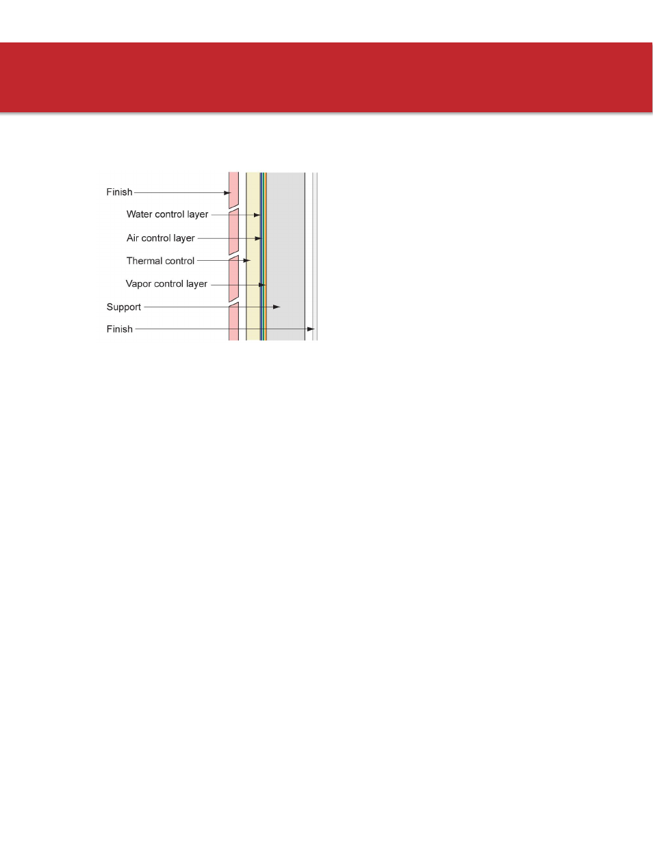
The “Perfect” Wall
The support/control/finish components of a typical
enclosure assembly are presented in a conceptually
“perfect” sequence in Figure 1.
The concept diagram shows an exterior finish layer
(the “cladding”) outside of the thermal, air, vapor,
and water control layers, which in turn are to the
exterior of the building structure and interior finishes.
By locating the heat flow control layer (insulation)
on the exterior of the structure and by locating the
combined air, water, and vapor control layers
between the structure and the insulation, the
structure and control layers are protected from UV exposure, impact, and temperature extremes,
thereby increasing the durability of the critical control layers. Such a strategy works well in all climate
zones, from Northern heating-dominated climates to hot and humid Southern climates.
Most residential walls include insulation in the structural cavity – which doesn’t follow the sequence of
layers described above. The typical residential wall is a balance of performance, cost, and constructability
issues.
Residential structures typically use a relatively non-conductive structural frame—the structure is wood
and wood material based. Cavity fill insulation is also typically less expensive and since the space for
insulation is provided by the structural cavity, there is no need for special attachment details. There is a
performance compromise with this approach, however, because the insulation within the structural
cavity lowers the temperature of the exterior sheathing during wintertime conditions, increasing the risk
of condensation. This risk can be managed with the use of insulating sheathing and is described in more
detail in the following sections.
The idea of the perfect wall is intended to guide designers on the proper principles during concept design.
The same approach can be extended for other enclosure elements such as roofs and foundations and
should be used to ensure continuity of the enclosure control layers when designing details describing the
connection between enclosure components such as control joints, window and mechanical penetrations.
The details provided in this guide use this approach.
Figure 1: The "perfect" wall