5 wiring diagram in the car – Robustel iGT06 User Manual
Page 13
Robustel GoSafe iGT06 User Guide
RT_iGT06_UG_v01.00
07.12.2011
12 / 29
Confidential
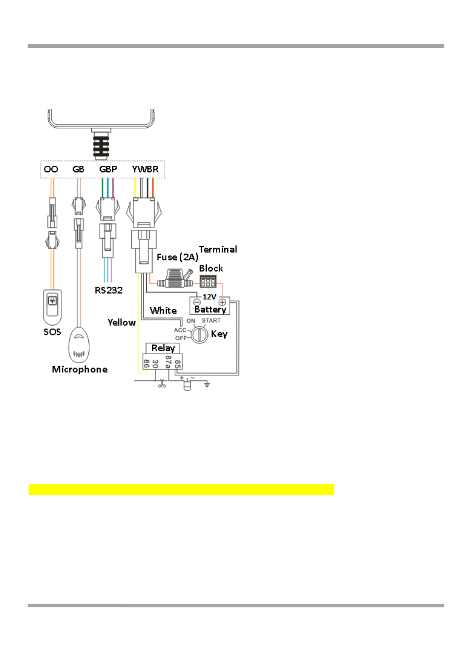
2.5 Wiring Diagram in the Car
Please connect the tracker according to follow picture.
Relay wiring notice:
Connect the relay to the pump according to follow:
1. Connect the thin white line (85) to the vehicle positive wire (+12V);
2. Connect the thin yellow (86) to the relay control line;
3. Cut off the pump positive line, connect the pump positive line to the relay NC (thick green line 87a);
4. Connect the opposite side of the cut‐off pump line to the relay COM (thick green line 30).
Note: We provide 12VDC relay accessory, which can connect to 12VDC car battery only.
Other wires:
1. Power, ACC and cut off fuel line (4 PIN)
a. The tracker can work with 9‐36VDC, please use the original power cable in the package. Connect the red
cable to positive power and black cable to negative power. Please ground the negative power separately.
b. Connect the orange color ACC cable to the vehicle ACC switch. The tracker’s arm status is relating to the ACC
status. If do not connect to ACC line, vehicle will enter into arm status, and tracker will send out alarm when
there are vibrations in the vehicle. Please parallel connect ACC line to power positive and keep it at high level