RKI Instruments GD-K77D User Manual
Page 12
7 • Description
Model GD-K77D
Operator’s Manual
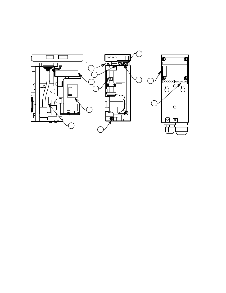
Internal and Back Panel Components
Refer to the diagram below for the location of Model GD-K77D internal and back panel
components, which are described below. After each component name is a number, which
corresponds to the same number in the diagram.
Figure 3: Internal Components
Power Switch (10). Turns power on or off to the Model GD-K77D.
Power Fuse (11). Protects the Model GD-K77D from a power overload.
Mode Switch (12). Toggles the Model GD-K77D’s operating mode between detection and
maintenance. When the Model GD-K77D is being used for gas detection, the Model GD-
K77D is in normal operation; when performing maintenance on the Model GD-K77D, use
this switch to put the unit into Maintenance Mode.
Test/Set Switch (13). This switch has several functions in Maintenance Mode.
FLOW ADJ Switch (
▲
/
▼
) (14). Increases or decreases the gas flow rate to the Model
GD-K77D when the unit is in normal operation. Gas flow adjustments are made when the
flow ball is outside the red flow lines. When the flow ball is above the top flow line, press
the FLOW ADJ switch down to reduce the flow rate. When the flow ball is below the
bottom flow line, press the FLOW ADJ switch up to increase the flow rate. This switch is
also used to increase or decrease parameters in Maintenance Mode.
Pump (15). Draws the sample gas by suction to the sensor inside the Model GD-K77D.
Lithium Battery (16). Provides a bias voltage to the Model GD-K77D sensor in the event
of a power outage or a drop in line voltage.
13
10
20
Detector Unit
Side View
11
18
16
14
17
19
15
Wall Mounting
Bracket
Front View
Detector Unit
Front View
12