Wiring the gd-70d to a controller – RKI Instruments GD-70D4X-XX User Manual
Page 8
5 • Model GD-70D4X-XX Sample Draw Transmitter
CAUTION:
Avoid loops or slumps in the incoming sample line. To reduce response time, keep the
incoming sample line as short as possible.
3.
Install 1/4’’ O.D. x 1/8” I.D. Teflon PTFE sample tubing to the gas out fitting. Route
the opposite end of the tubing to an open area where the sample can safely disperse or
to an exhaust duct.
Wiring the GD-70D to a Controller
WARNING: Always verify that power to the GD-70D4X-XX and to the controller are
off and that the controller’s and GD-70D’s power switches are in the off
position before making wiring connections or adjustments.
1.
Turn off power to the controller.
2.
Place the controller’s and GD-70D’s power switches in the OFF position.
3.
Use the conduit hubs at the bottom of the GD-70D4X-XX for routing power and signal
cables into the enclosure. Route any relay wiring through one conduit hub, and a 3-
conductor shielded cable, or three wires in conduit, for controller connections through
the other conduit hub to minimize crosstalk.
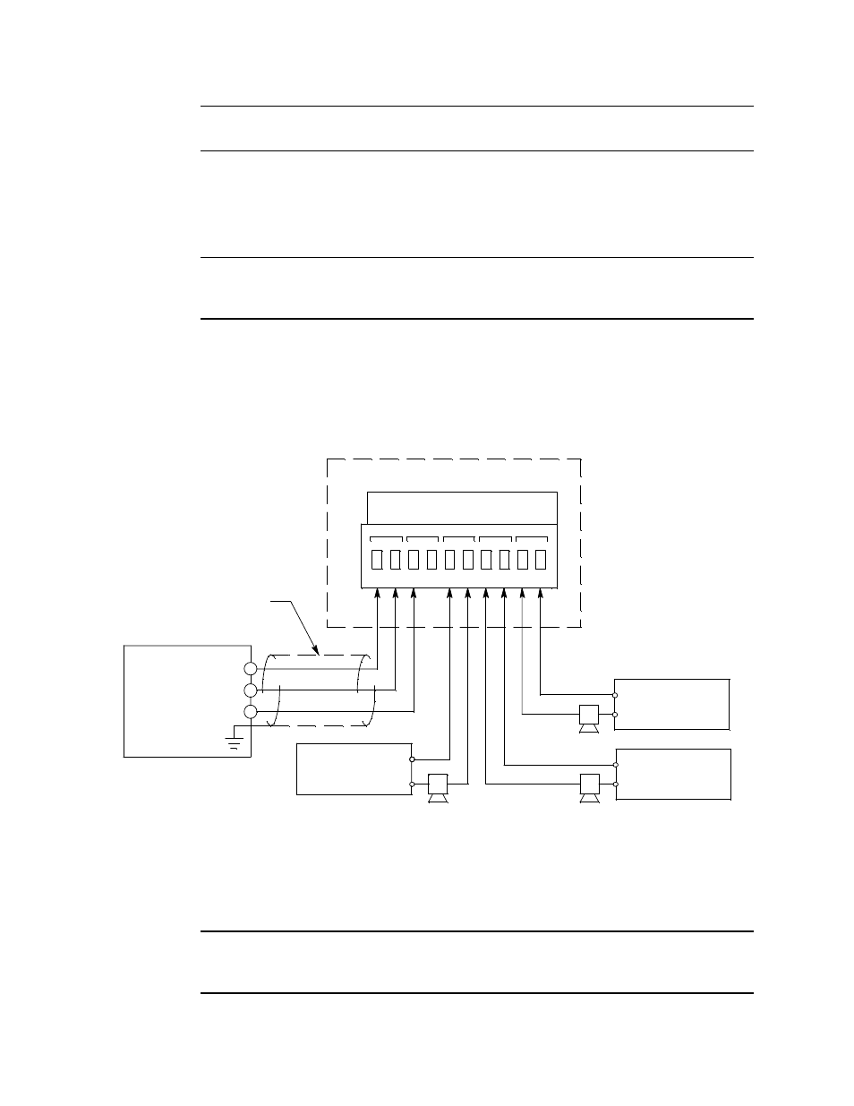
Figure 4:
External Wiring
4.
If shielded cable is used for controller wiring, connect the cable shield’s drain wire to
a chassis ground at the controller, but do not connect it at the GD-70D4X-XX.
CAUTION:
Leave the cable shield’s drain wire insulated and disconnected at the
GD-70D4X-XX. You will connect the opposite end of the cable shield’s drain wire at
the controller.
4 - 20 mA In (S)
- (DC Ground)
Cable Shield
10
9
8
GD-70D Terminal Strip
+ 24 VDC
-
FAULT
ALM2
4-20mA
DC24V
ALM1
-
(+) H
+
+
7
6
5
4
3
2
1
(+) H
External Power
Source
(-) N
Alarm
Device
External Power
Source
(-) N
External Power
Source
(+) H
Controller
Alarm
Device
Alarm
Device
(-) N