2495rk, 2498rk, Wiring the h – RKI Instruments 65-2498RK User Manual
Page 7: S detector to a controller
65-2495RK/65-2498RK H
2
S Detector • 7
NOTE:
If your application does not require a specific mounting site, mount the detector
at approximately breathing level.
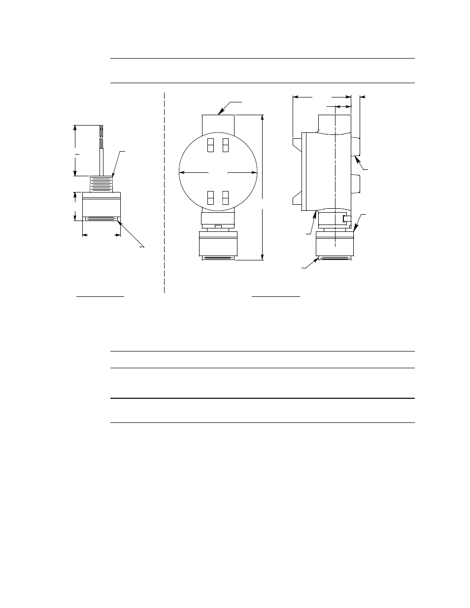
Figure 3: Outline & Mounting Dimensions, 65-2495RK & 65-2498RK
2.
At the mounting site you select, hang or mount the junction box with the detector
facing down (see Figure 3).
CAUTION:
Mount the H
2
S detector with the detector facing down (see Figure 3.)
Wiring the H
2
S Detector to a Controller
WARNING: Always verify that power to the controller is OFF before you make wiring
connections.
1.
Turn off the controller.
2.
Turn off or unplug power to the controller.
3.
If the detector is mounted remotely from a controller using the junction box, proceed
to step 4.
If the detector is mounted directly to a controller, it is normally factory wired. Confirm
that the detector’s black and red wires are connected to the appropriate controller
detector terminals and skip to “Start Up” on page 9. See Figure 4, the controller
operator’s manual, and the controller’s detector head specification sheet for the 65-
2495RK detector for the wiring connections.
4.
Remove the junction box cover.
Rubber
Spacer, 3X
.38
.75
2.70
2
H S
Detector
7.30 .25
3.65
3/4" NPT
+
Ø 1.75
1 1/2-20 Thread for
Calibration Cup
65-2495RK
3/4 NPT
Conduit Hub
65-2498RK
1 1/2-20 Thread for
Calibration Cup
Junction
Box
1.32
.75
6.80 Max