Parts list – RKI Instruments 65-2483RK User Manual
Page 37
65-2483RK Multi Point Detector • 33
5.
Set the fresh air reading according to the controller operator’s manual.
6.
Unscrew the regulator from the zero air calibration cylinder. Leave the sample tubing
connected to the regulator and the calibration cup.
Setting the Zero Reading
1.
Screw the regulator into the 100% nitrogen calibration gas cylinder. Make sure the
regulator is off. It is off when the on/off knob is turned all the way clockwise.
2.
Follow the directions in the controller operator’s manual for setting the zero reading.
3.
When the directions call for exposing the detector to gas, turn the regulator’s on/off
knob counterclockwise to open it. Gas will begin to flow.
4.
Allow gas to flow for 2 minutes.
5.
Turn the regulator’s on/off knob clockwise to close it.
6.
Set the zero reading according to the controller operator’s manual.
7.
Unscrew the regulator from the cylinder.
Returning to Normal Operation
1.
Unscrew the calibration cup from the oxygen detector.
NOTE:
For convenience, leave regulator and calibration cup connected by the sample
tubing.
2.
When the controller display reading rises above the alarm points, return the
controller to normal operation.
NOTE
: If you do not allow the gas reading to rise above the alarm points, then unwanted
alarms may occur.
3.
Verify that the controller display reading increases and stabilizes at 20.9% oxygen.
4.
Store the components of the calibration kit in a safe and convenient place.
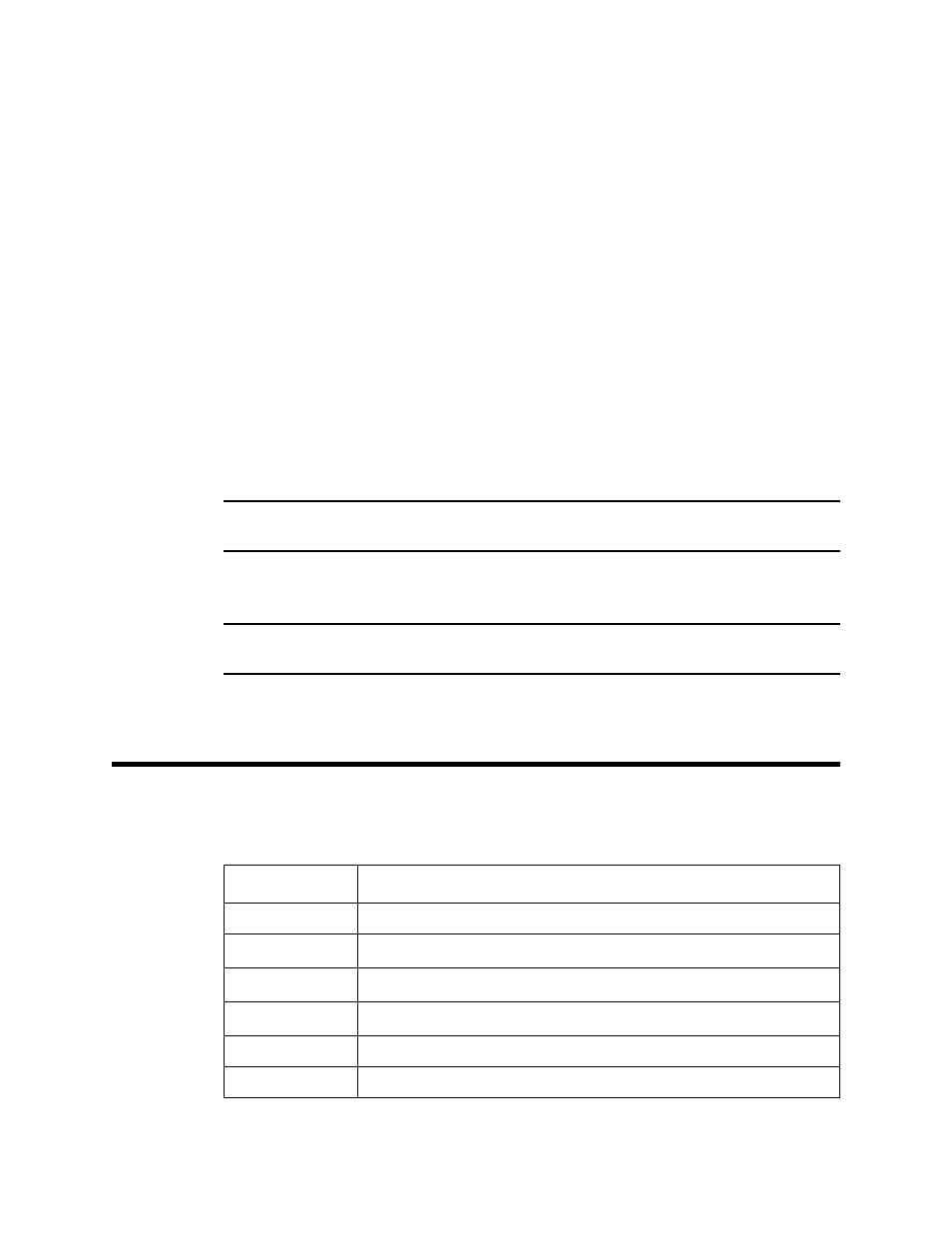
Parts List
Table 5 lists replacement parts and accessories for the multi-point detector.
Table 3: Parts List
Part Number
Description
06-1248RK-03
Calibration kit sample tubing, 3 ft. length
07-0033RK
Detector housing cap gasket (for H
2
S, O
2
and CO detectors)
07-0203RK
Rubber retaining boot (for CO and H
2
S detectors)
14-2101RK
Spacer between H
2
S sensor and rubber boot
33-7101RK
Charcoal filter disk (for CO detector)
61-0190RK-HC
IR HC LEL replacement detector