S detector – RKI Instruments 65-2427RK-05 User Manual
Page 7
65-2427RK-05 H
2
S Detector • 3
65-2423RK-05 H
2
S Detector
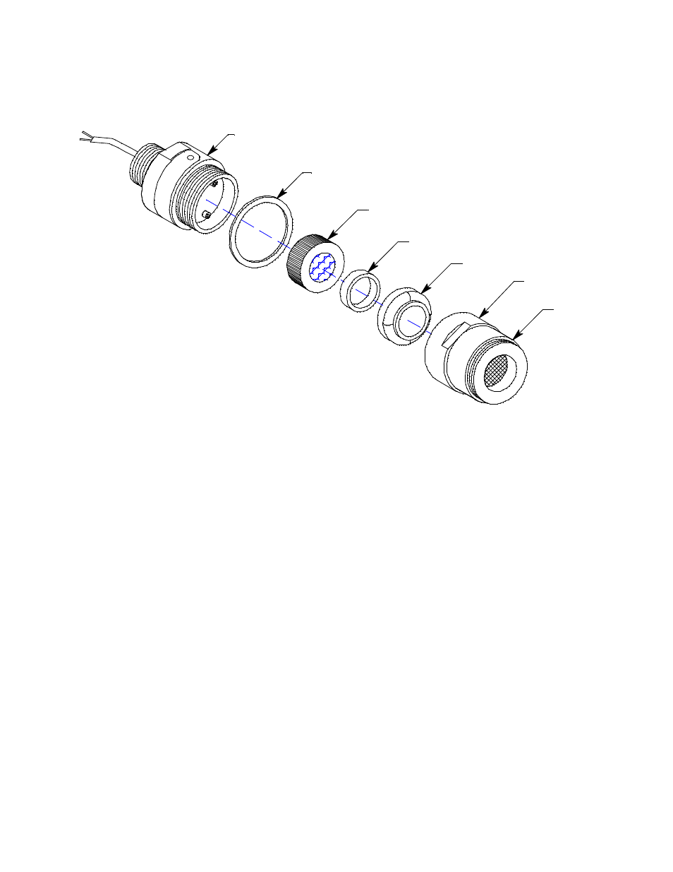
The 65-2423RK-05 H
2
S detector consists of the detector housing body, detector housing
cap, cap gasket, rubber boot, spacer, and the plug-in sensor.
Figure 2: H
2
S Detector Component Location
Detector Housing Body, Housing Cap, & Cap Gasket
The detector housing body protects the sensing components within the housing. Use the
3/4” NPT mounting threads at the top of the housing to screw the H
2
S detector into the
bottom conduit hubs of the junction box. Use the removable cap near the bottom of the
housing to access the sensor for maintenance or replacement. The cap protects the sensor
from damage and includes a flame arrestor which contains any sparks which may occur
within the detector housing. A cap gasket seals the interface between the housing and cap.
A flame arrestor guard is permanently bonded to the cap.
Two wires extend from the top of the detector housing body. Use these wires to connect
the H
2
S detector to the junction box terminal strip. The housing includes a four-socket
pattern. This socket pattern accepts the sensor’s four pins to secure the sensor within the
detector housing. A pre-amplifier, located between the sockets and two interconnect
wires, conditions the sensor’s signal before the signal reaches the controller.
Rubber Boot and Spacer
A rubber boot and spacer are installed between the detector housing cap and the sensor.
They help ensure that the detector remains plugged into the detector housing body.
Plug-In Sensor
The sensor is secured within the sensor housing by four pins. Through a series of chemical
and electrical reactions, the sensor produces an electrical output that corresponds to the
detection range of the detector.
Spacer
Rubber Boot
H2S Plug-in Sensor
Flame
Arrestor
Guard
Detector
Housing Cap
Detector Housing Body
Cap Gasket