Parts list – RKI Instruments 61-1000RK-05 User Manual
Page 15
61-1000RK-05 Combustible Gas Detector • 11
Setting the Response Reading
1.
Follow the directions in the controller’s operator’s manual for setting the response
reading (span).
2.
When the directions call for exposing the detector to gas, turn the regulator’s on/off
knob counterclockwise to open it.
3.
Allow the gas to flow for one minute before continuing with the directions.
4.
After setting the response reading, turn the regulator’s on/off knob clockwise to close
it.
5.
Unscrew the regulator from the cylinder.
Returning to Normal Operation
1.
Unscrew the calibration cup from the detector.
NOTE:
For convenience, leave regulator and calibration cup connected by the sample
tubing.
2.
When the controller display reading falls below the alarm points, return the controller
to normal operation.
NOTE
: If you do not allow the gas reading to decrease below the alarm points, then
unwanted alarms may occur.
3.
Verify that the controller display reading decreases and stabilizes at 0 %LEL.
4.
Store the components of the calibration kit in a safe and convenient place.
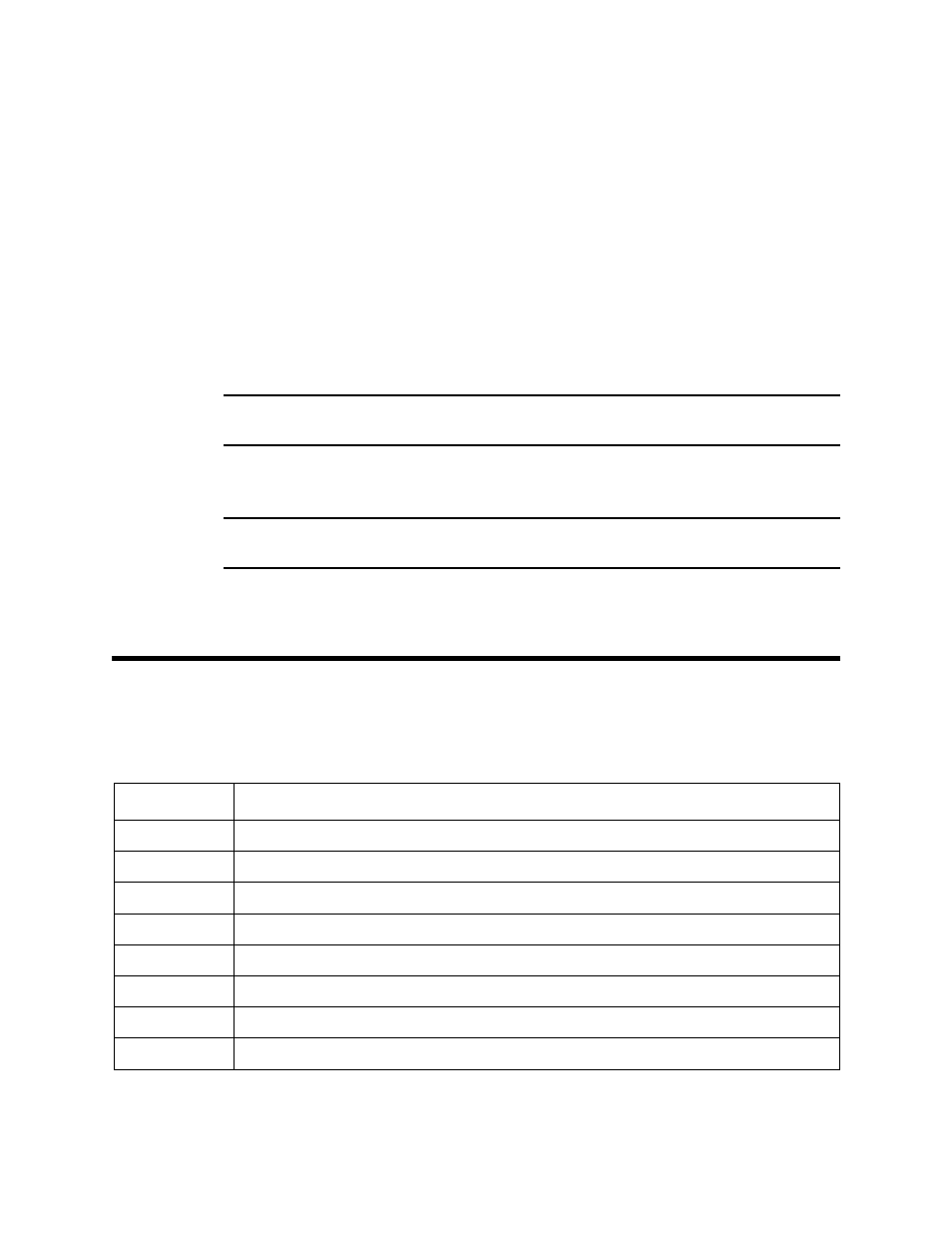
Parts List
Table 3 lists replacement parts and accessories for the 61-1000RK-05 combustible gas
detector.
Table 3: Parts List
Part Number
Description
18-0400RK-01
Junction box with spacers
61-0140RK-05
Replacement combustible gas detector
71-0087RK
61-1000RK-05 Combustible Gas Detector Operator’s Manual (this document)
81-0007RK-01
Calibration cylinder (15% LEL Hexane in air, 34 liter)
81-0012RK-01
Calibration cylinder (50% LEL Methane in air, 34 liter)
81-0076RK-01
Zero air calibration cylinder (34 liter)
81-1050RK
Regulator with gauge and knob, 0.5 LPM (for 17 and 34 liter calibration cylinders)
81-1117RK
Calibration cup