RKI Instruments 35-3010RKA-06 User Manual
Page 10
6 • 35-3010RKA-06 Sample-Draw Detector
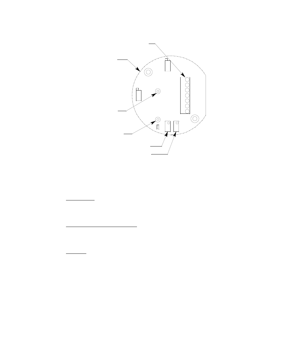
Figure 3: LEL Transmitter
LEL Transmitter
The LEL transmitter is mounted above the main circuit board. It consists of the span pot,
zero pot, one internally wired terminal strip, and the test points.
Span/Zero Pots
The span and zero pots are located at the bottom edge of the transmitter and are used for
calibration. Use the span pot to make adjustments to gas response readings and the zero
pot to make adjustments to the zero reading.
Transmitter Interconnect Terminal Strip
The transmitter interconnect terminal strip is the seven-point terminal strip near the right
edge of the transmitter. The transmitter is factory wired to the sensor and main circuit
board.
Test Points
The test points are located on the left side of the transmitter and are labeled TP+ and TP-.
A 100 mV - 500 mV output is available at these test points for use during calibration.
Preamp Circuit Board
The preamp circuit is used to connect the H
2
S sensor to the main circuit board and to
secure the sensor in the flow block. Two cables mate to the main circuit board: the one on
the left is for the CO sensor signal and the one of the right is for the H
2
S sensor signal.
Since there is no CO channel, the cable on the left is not used.
LEL Transmitter
Interconnect
Terminal Strip
Zero Pot
Span Pot
Test Point TP-
Test Point TP+