RKI Instruments 35-3010RK-03 User Manual
Page 10
6 • 35-3010RK-03 Sample-Draw Detector
Carbon Monoxide Sensor
The carbon monoxide gas sensor is installed in the upper left side of the flow block. It has
4 pins which mate with sockets in the preamp circuit board.
Hydrogen Sulfide Gas Sensor
The hydrogen sulfide gas sensor position is located in the upper right side of the flow
block. In the 35-3010RK-03, the hydrogen sulfide gas sensor position in the flow block is
occupied by a dummy sensor.
Preamp Circuit Board
The preamp circuit is used to connect the CO sensor to the main circuit board and to
secure the sensor in the flow block. Two cables mate to the main circuit board: the one on
the left is for the CO sensor signal and the one of the right is for the H
2
S sensor signal.
Since the H
2
S sensor is replaced with a dummy plug in the 35-3010RK-03 the H
2
S sensor
signal cable carries no signal in this version of the 35-3010RK.
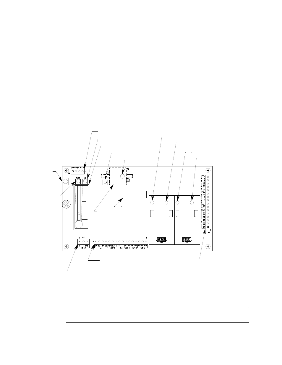
Main Circuit Board
Figure 3: Main Circuit Board
The main circuit board includes the interconnect terminal strip, sensor/transmitter
terminal strip, amp 1 circuit, amp 2 circuit, pump terminal strip, relay, and reset switch.
NOTE:
The flowmeter and status lights are mounted to the main circuit board but are
considered part of the flow system.
Test Point CAL + 2
Amp 1
(CO)
Zero
Span
Zero
Fail LED
Sensor/Transmitter
Terminal Strip
Pressure Switch
Reset
Switch
Pilot LED
Amp 2
(H2S)
Span
Test Point CAL + 1
Test Point CAL - 2
Test Point CAL - 1
AC Terminal
Strip Not Used
Interconnect Terminal
Strip
Low Flow Adjust
Flow Adjust Pot
Flowmeter
Pump Terminal Stip
Relay