RKI Instruments 35-3010RK-02 User Manual
Page 10
6 • 35-3010RK-02 Sample-Draw Detector
CO Dummy Plug
The CO sensor position in the flow block is occupied by a plastic dummy plug in the
35-3010RK-02.
Hydrogen Sulfide Gas Sensor
The hydrogen sulfide gas sensor is installed in the upper right side of the flow block. It
has 4 pins which mate with sockets on the preamp circuit board.
Preamp Circuit Board
The preamp circuit is used to connect the CO and H
2
S sensors to the main circuit board
and to secure the sensors in the flow block. Two cables mate to the main circuit board: the
one on the left is for the CO sensor signal and the one of the right is for the H
2
S sensor
signal. Since the CO sensor is replaced with a dummy plug in the 35-3010RK-02 the CO
sensor signal cable carries no signal in this version of the 35-3010RK.
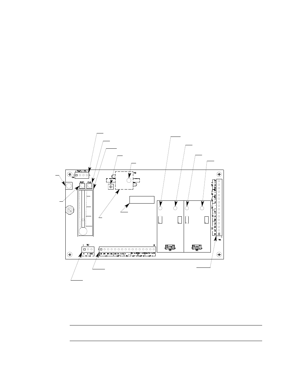
Main Circuit Board
Figure 3: Main Circuit Board
The main circuit board includes the interconnect terminal strip, sensor/transmitter
terminal strip, amp 1 circuit, amp 2 circuit, pump terminal strip, relay, and reset switch
(see Figure 3).
NOTE:
The flowmeter and status lights are mounted to the main circuit board but are
considered part of the flow system.
Test Point CAL + 2
Amp 1
(CO)
Zero
Span
Zero
Fail LED
Sensor/Transmitter
Terminal Strip
Pressure Switch
Reset
Switch
Pilot LED
Amp 2
(H2S)
Span
Test Point CAL + 1
Test Point CAL - 2
Test Point CAL - 1
AC Terminal
Strip Not Used
Interconnect Terminal
Strip
Low Flow Adjust
Flow Adjust Pot
Flowmeter
Pump Terminal Stip
Relay