RKI Instruments 35-3001A-09 User Manual
Page 10
6 • 35-3001A-09 Oxygen/Hydrogen Sulfide Sample-Draw Detector
Oxygen Amplifier
The amplifier converts the electrical output from the detector to a 4 to 20 mA signal that
corresponds to the detection range and transmits the signal to a gas monitoring controller. The
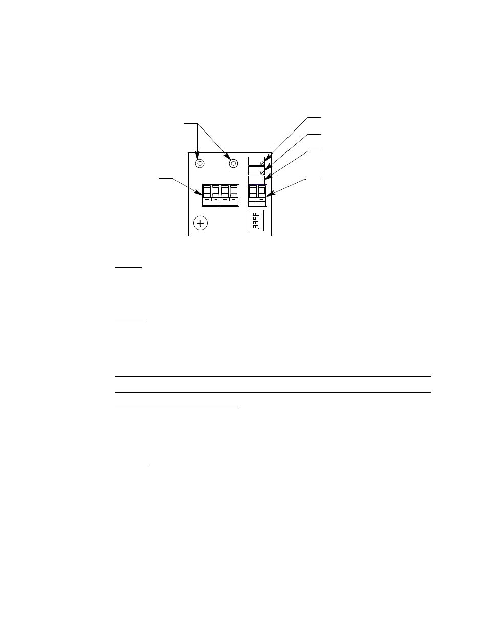
amplifier is mounted on the top middle edge of the main circuit board. It consists of the zero pot,
span pot, controller terminal strip, detector terminal strip, and test points.
Figure 3: Oxygen Amplifier Component Location
Zero Pot
The zero pot is located in the upper right corner of the amplifier (see Figure 3). Use a small flat
blade screwdriver to turn the zero pot’s adjustment screw and adjust the amplifier’s zero (oxygen
free) output during the calibration procedure. Turn the adjustment screw clockwise to increase the
zero output and counterclockwise to decrease the zero output.
Span Pot
The span pot is located below the zero pot (see Figure 3). Use a small flat blade screwdriver to turn
the span pot’s adjustment screw and adjust the amplifier’s fresh air output during the start up and
calibration procedure. Turn the adjustment screw clockwise to increase the fresh air output and
counterclockwise to decrease the fresh air output.
CAUTION:
The amplifier includes an additional pot. It is factory-set. Do not adjust it.
Controller and Detector Terminal Strips
The controller terminal strip and detector terminal strip are two- and four-position plug-in style
terminal strips, respectively. The controller terminal strip is located on the right side of the
amplifier and the detector terminal strip is to the left of it. Both terminal strips are factory wired to
the detector/amp terminal strip on the main circuit board.
Test Points
The test points are on the left side of the amplifier (see Figure 3). The test points produce a 100 mV
to 500 mV output that corresponds to the sample-draw detector’s 4 to 20 mA output. Use the test
points and a voltmeter to measure the amplifier’s output during the start-up and calibration
procedures. The black test point in the upper left corner is the negative (-) test point and the red test
point to the left of the zero and span pots is the positive (+) test point.
Flow Baffle
A flow baffle is located in front of the hydrogen sulfide sensor. Its function is to isolate the
hydrogen sulfide sensor from vibrations in the flow line that are caused by the pump.
Factory Set Pot
Span Pot
Zero Pot
Test Points
100-500 mV Range
S
SIG/PWR
TOXIC
Controller
Terminal Strip
OXY
Detector
Terminal
Strip