RKI Instruments 35-3001A-01-01 User Manual
Page 20
16 • 35-3001A-01-01 Methane Sample-Draw Detector
9.
Turn on power to the controller and place it into normal operation.
10. Turn on the controller.
CAUTION:
Allow the replacement sensor to warm up for 5 minutes before you continue.
11. Calibrate the replacement sensor as described in “Calibration” on page 18.
Replacing the Amplifier
1.
Turn off the controller.
2.
Turn off power to the controller.
3.
Open the housing door of the sample-draw detector.
4.
Remove the detector and controller plug-in terminal strips by grasping the sides of the strips
with your fingers. Let the terminal strips hang by their connected wires while you replace the
amplifier.
5.
Unscrew the screw in the lower left corner of the amplifier and remove the screw, lock washer,
and flat washer. Be careful not to lose any of these parts.
6.
Remove the old amplifier from the main circuit board.
7.
Install the new amplifier in the same orientation as the old amplifier. See Figure 1.
8.
Reinstall the screw, lock washer, and flat washer you removed in step 5.
9.
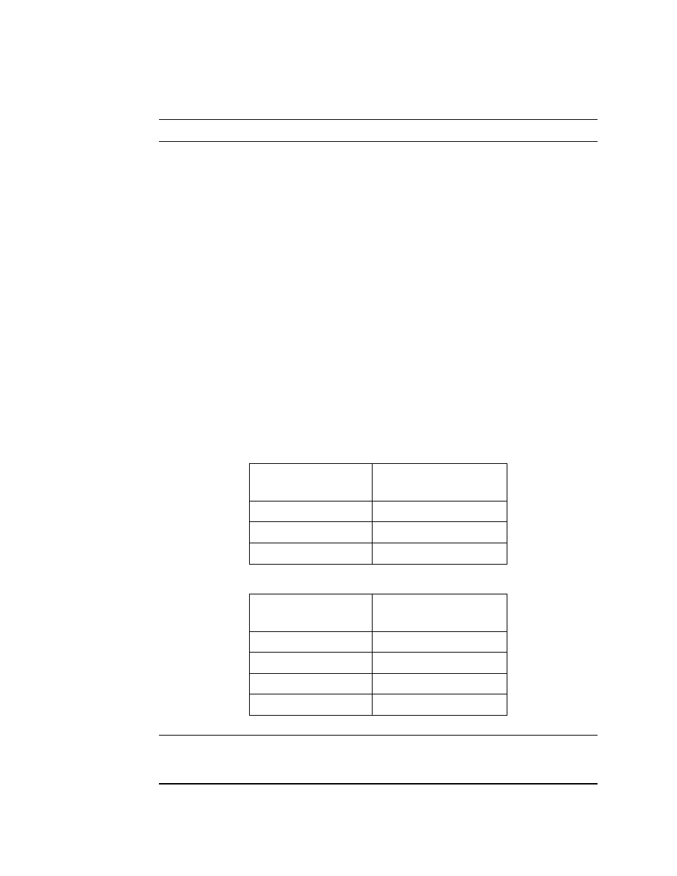
Install the detector and controller plug-in terminals strips into their sockets on the new
amplifier. If controller leads or detector cable leads were removed from the plug-in terminal
strips during this procedure, refer to Table 2 and Table 3 below.
NOTE: When the sample-draw detector is first powered up with a new amplifier, the initial
output may be either high or below zero depending on the setting of the zero pot. Be sure
to make arrangements so that this does not cause unwanted alarms.
Table 2:Reconnecting the Amplifier
to the Detector/Amp Terminal Strip
Amplifier Controller
Terminal Strip
Detector/Amp Terminal
Strip on Main PCB
PWR/SIG “-”
-
PWR/SIG “S”
S
PWR/SIG “+”
+
Table 3:Reconnecting the IR Methane Sensor to the Amplifier
Amplifier Detector
Terminal Strip
Detector Lead
DETECTOR “R”
RED
DETECTOR “W”
WHT
DETECTOR “G”
GREEN
DETECTOR “B”
BLK