RKI Instruments 35-3000RK-LEL User Manual
Page 11
35-3000RK-LEL Combustilbe Gas Sample-Draw Detector • 11
CAUTION:
If using shielded cable, leave the cable shield’s drain wire insulated and disconnected
at the sample-draw detector. You will connect the opposite end of the drain wire at
the controller.
7. Route the cable or wires in conduit leading from the sample-draw detector through
one of the conduit hubs at the controller.
CAUTION:
Do not route controller power wiring and detector wiring through the same hub.
The power cable may disrupt the transmission of the sensor signal to the controller.
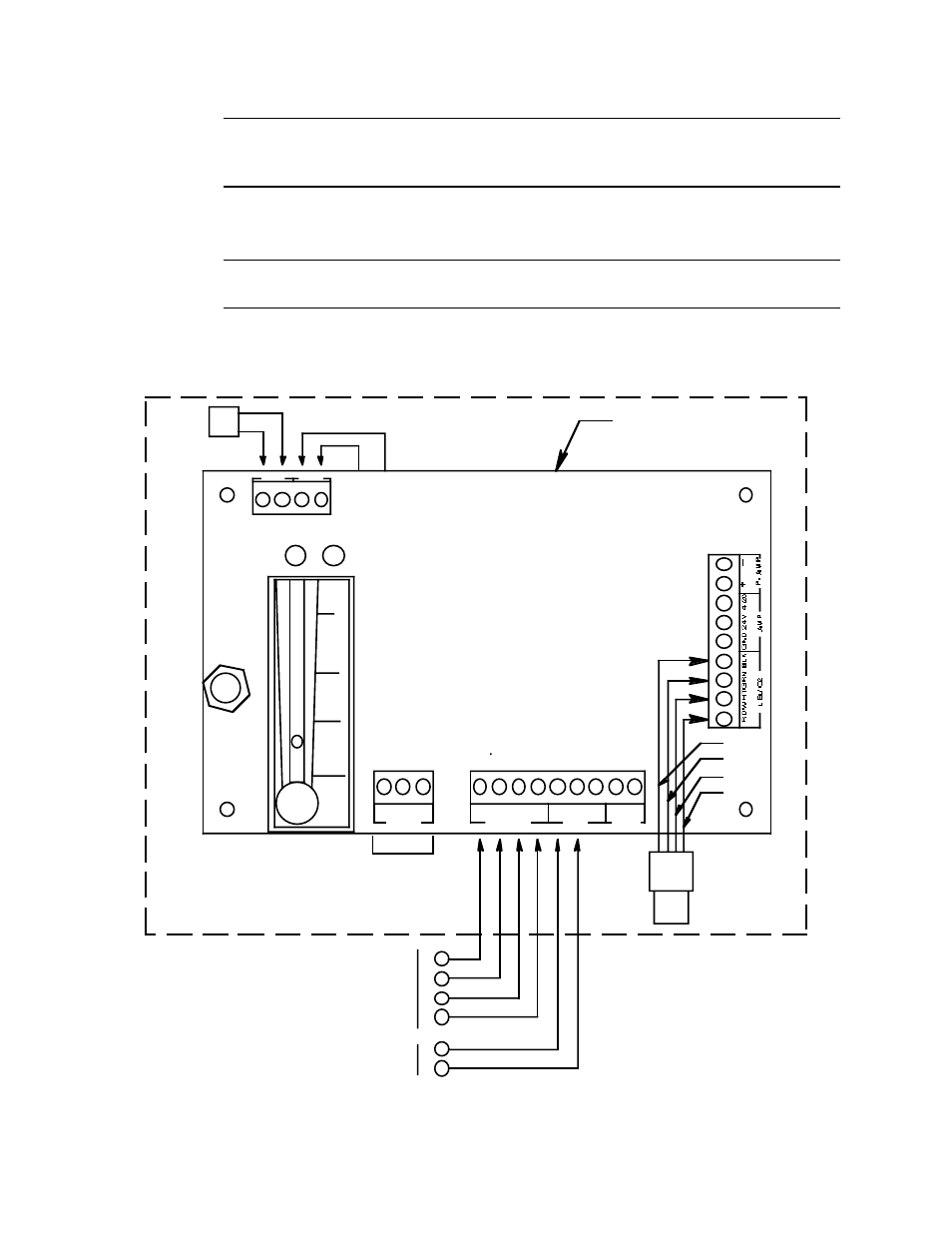
8. Connect the wires to the applicable detector terminal strip and power terminals at the
controller as shown in Figure 4.
Figure 4: Wiring the Sample-Draw Detector to a Controller
Controller LEL
Sensor Terminals
Black
Green
Controller Terminals
Pump.,
Internally Wired
Combustible
Gas Sensor,
Internally Wired
Red
- (DC -)
+ 24 VDC
White
Red
Pressure Switch,
Internally Wired
Sample-Draw Detector
Main Circuit Board
A CTerminal
Strip Not Used
On This
Version
White
Green
Black
PUMP
115VAC
PSW
P- AMP
AMP
LEL/ O2
H
N GND
GND
LEL Sample-Draw Detector Housing
+
_
4/20
24V
RD WHT GRN BLK