RKI Instruments 49-8103RK User Manual
Page 6
49-8103RK Standby Battery • 6
wiring to the Beacon 200. Note which wire is positive and which wire is negative.
8.
A short factory installed jumper wire terminated with push-on lugs connects the two
batteries in the standby battery. Remove this wire from one of the battery terminals
and make sure it is not contacting the terminal.
9.
When the standby battery is shipped from the factory, the ends of the two wires
provided for external wiring connections are covered with shrink tubing to prevent
shorting of the batteries during shipment. Remove the shrink tubing and strip the end
of each wire.
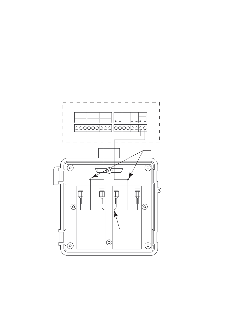
10. Use the wire nuts provided with the standby battery to connect the positive and
negative wires in the standby battery to the positive and negative wires coming from
the controller as shown in Figure 3 and Figure 4.
Figure 3: Wiring the Standby Battery to a Beacon 110
NO NC C
NO NC C
NO NC C
FAIL
ALARM-1
ALARM-2
ALARM
BUZZER
ALARM
RESET
4-20 mA
OUTPUT
EXT DC
24V BATT
Beacon 110 Housing
Alarm Terminal Strip
Controller Terminal Strip
+
+
Connections Made With
Wire Nuts Provided
Standby Battery
Shown Without
Door
Factory
Installed
Jumper