Wiring, Important, Air handler to multi stage compressor – Pro1 WW160W User Manual
Page 7: Turn off power while wiring
7
5
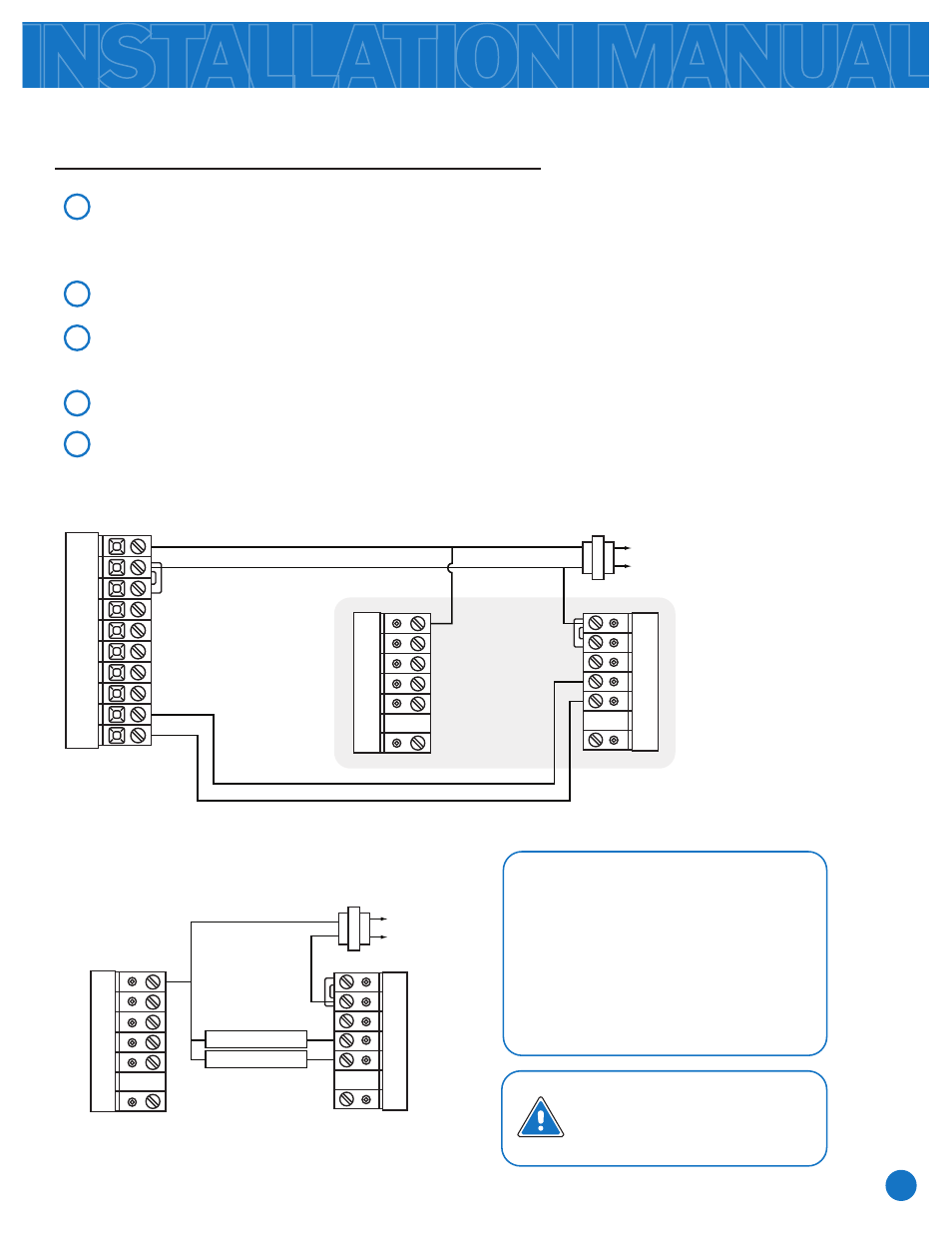
WIRING
1ST STAGE RELAY
2ND STAGE RELAY
1
2
3
4
Air Handler to Multi Stage Compressor
Install the Input Module in a location that is convenient to wire to the system control board.
(this is the board that normally has the wire from the condensing unit connected to it.)
Connect 24VAC to the R and C on the output module.
Install the output module in a location that is convenient to wire to the compressor relays.
Connect the terminals from the furnace control board to the appropriate terminals on the
input module. (Y1 to Y1, ect...)
Connect the terminals from wireless wire Output Module to the compressor relays.
Test the system.
Furnace Board
Wireless Wire
Input Module
Power Supply
C
RC
RH
W2
W1/E
B
O
G
Y1
Y2
C
L2
L1 (HOT)
R
Rh
Rc
G
Y1
Y2
Out 2
C
O
B
W1/E
W2
Out 1
Wireless Wire
Output Module
Rh
Rc
G
Y1
Y2
In 2
C
O
B
W1/E
W2
In 1
C
L2
L1 (HOT)
R
Wiring Note:
for Heat Pumps with a
defrost cycle connect the
Defrost terminal to
Input 1
on the
Output Module and
connect
Out 1 on the Input
Module to the appropriate
terminal on the air handler.
Important:
Turn off power while wiring.