Wireless modules quick reference – Pro1 WW160W User Manual
Page 2
2
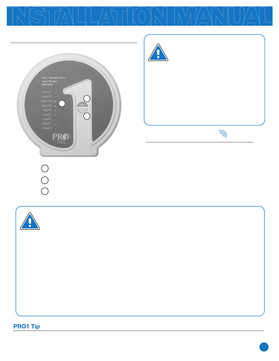
Getting to know the Wireless Wire
®
Modules
Terminal Lights
1
2
Module Button
Visit our website at www.pro1iaq.com to learn more about our other wireless family of products
Blue Indicator Light
3
1
2
3
Important:
Both wireless modules must have
24VAC power connected on R
and C. These modules can only
switch 24VAC power. Wireless
signal is one way from
Input
Module to Output Module for all
terminals except
Input 1 and
Input 2. Terminals Input 1 and
Input 2 have a one way signal to
Output 1 and Output 2.
Notes on Wireless Wire®
When the
Y1
on the
Input
module receives a 24VAC signal it sends a wireless command to the
output module and it closes the
Output
modules
Y1
. This logic also applies to Y2, W1, W2, G, B & O.
When the
Input 1
on the
Output
module receives a 24VAC signal it sends a wireless
command to the
Input
module and it closes the
Output 1
terminal. This logic also applies to Input
2/Output 2.
The
terminal lights
on the front of the module indicate when the associated relay is closed.
The
blue indicator light
will be on if communication is established and working.
The
blue indicator light
flashes when the unit is sending a signal.
The
blue indicator light
will be off if the module has not communicated for 1 hour or
24VAC has been lost.
All inputs will be turned off after 1 hour if the communication link is continuously lost.
Hold
Output
Module Button
for 5 seconds.
The
Blue Indicator Light
will flash while
waiting for a signal from the
Input
module.
Hold
Input Module Button
for 5 seconds.
The
Blue Indicator Light
will be continously on
to show communication has been established.
WIRELESS MODULES QUICK REFERENCE
1.
2.
3.
4.
Connecting Wireless Wire
®