Multiquip 382V User Manual
Page 8
PAGE 8 — MODEL 314/382 FLEXIBLE SHAFT — PARTS & OPERATION MANUAL — REV. #0 (04/08/02)
MAINTENANCE
Daily Inspection
1. Following daily use remove any dirt and concrete from the
shaft, motor and head.
2. Inspect the unit for any damage to any of the three compo-
nents and have repaired before further use. Refer to the
respective instruction bulletins for repair of the power unit
and head.
3. Inspect the casing for any cuts or holes through the covering,
loose ferrules, or a permanent kink in the shaft. If any of these
conditions are found, replace the casing.
100 Hour Maintenance
1. Remove the shaft form the motor.
2. If the shaft is equipped with a quick disconnect coupling,
unscrew it from the casing ferrule. Threads are right
handed.
3. Unscrew the vibrator head from the shaft casing. Threads
are left handed. Heat should be used to loosen the
anaerobic sealant in the threads.
4. Pull the core out of the casing, wiping the grease off as it is
pulled form the casing.
5. Inspect the core for broken wires, a permanent set, or other
damage such as an area that shows high wear of having run
overheated. Replace with a new core if these conditions
exist.
6. Use the core to push a cleaning patch through the casing to
remove the old grease and any foreign matter.
7. Thoroughly clean the core if it is being reused.
8. Relube the core. Coat it with
DuBois "TPG"
lubricant or a
good grade of ball bearing grease. Only a light coating is
needed. CAUTION: DO NOT
"pack"
the shaft assembly
with grease. Excessive lubrication will cause overheating.
9. Reassemble using the reverse procedure.
10. When connecting the head to the casing, clean the mating
threads with an anaerobic sealant primer and allow to dry for
several minutes. Apply a ring of anaerobic sealant to the
middle of the casing ferrule threads. Screw the head tightly
to the casing and wait for one hour before using.
Connecting the QD Coupling to the Core.
1. Slide the core out of the casing far enough to thread the
spindle into the core fitting and tighten. If the connection is not
tight, the torque of the motor plus the load of the head will jam
the two fittings together, making it extremely hard to loosen
them for disassembly.
2. Thread the Q.D. coupling into the casing ferrule and tighten.
3. To connect the shaft assembly and Q.D. coupling to the
vibrator motor, pull up on the lock pin a d slide the shaft into
the end bell. Release the lock pin and give the shaft assembly
a twist to make certain the lock pin is seated in one of the 3
holes in the shaft coupling.
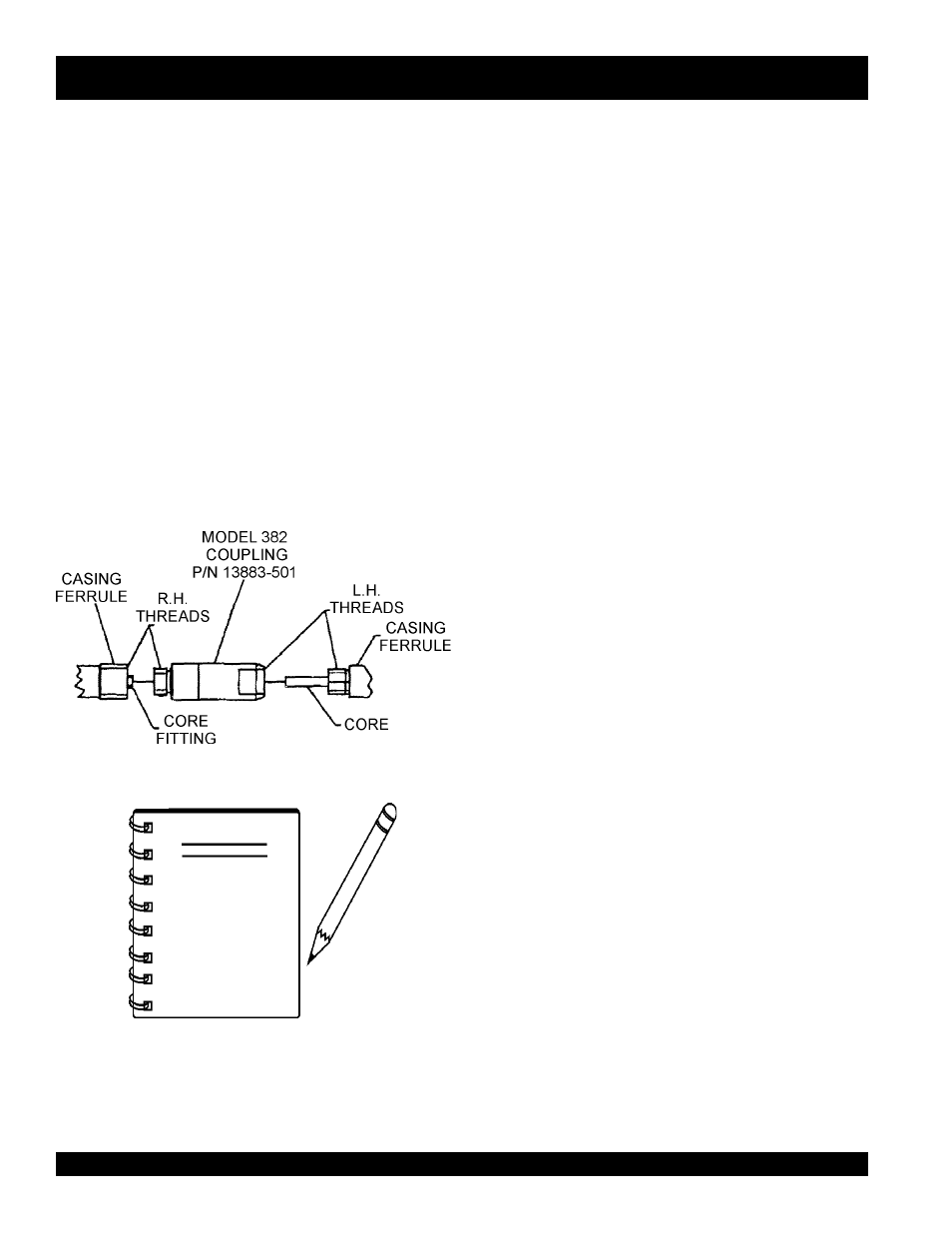
Connecting Two Flexible Shafts (Model 382)
1. Use coupling P/N 13883-501 when joining the two flexible
shafts (Model 382) together.
2. Connect both flexible shafts as shown in Figure 3.
When ordering core or
casing part numbers
use Table 2.
Example: (Model 314)
A complete Core and Casing Assembly
part num-
ber would be 13609. If a 12 foot shaft is desired, select
512. The new complete part number using a 12 ft. shaft
would be 1309-512.
NOTE
VIBRATOR SHAFT MODEL 314/382 — OPERATION/MAINTENANCE
Figure 3. Connecting Two Flexible Shafts