Multiquip 382V User Manual
Page 7
MODEL 314/382 FLEXIBLE SHAFT — PARTS & OPERATION MANUAL — REV. #0 (04/08/02) — PAGE 7
Preparation and Operation
1. Before connecting the flexible shaft to the vibrator motor
head, read and fully understand all of the safety and operat-
ing instructions for the flexible shaft, vibrator motor and the
head.
2. The flexible shaft is shipped from the factor ready to use.
3. Use only the combination of flexible shafts, motors and heads
shown in the Table 1 (specifications).
4. Operate the flexible shaft in a straight configuration as
possible. Sharp bends increase the load on the core and the
vibrator motor, which will result in early core failure and
possible damage to the vibrator motor.
5. When storing the flexible shaft, it is recommended that it be
stored flat, either laid out straight or in a large radius. Keep
the ends covered to keep out foreign matter. Check lubrica-
tion before each use.
6. CAUTION!: If the shaft begins to helix (buckle) excessively
during operation, stop and correct the problem, this is an
indication of an overload condition. The problem could be the
core or the head.
CONNECTING THE SHAFT
The following steps are for connecting the flexible shaft
(Model 314) to the 1 HP vibrator motor:
1. Warning!:
make certain
the vibrator motor us unplugged
and the OFF/ON switch is in the
OFF
position.
2. Slide the core out of the shaft casing far enough to allow it to
be screwed into the fitting adapter (
threads are right
handed
).
If the connection is not tight the torque of the motor plus the
load of the head will jam the fittings together, making it
extremely difficult to break the connection loose for disas-
sembly.
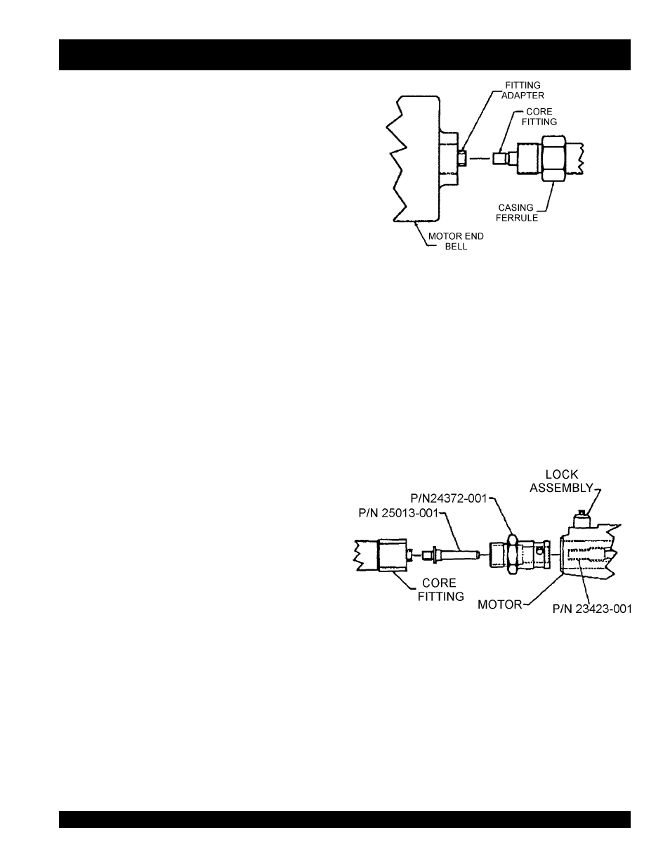
3. Screw the shaft casing ferrule into the motor end bell (threads
are right handed). See Figure 1.
The following steps are for connecting the flexible shaft,
Model 382 to a 2 or 3 HP vibrator motor:
5. Warning!:
make certain
the vibrator motor us unplugged
and the
OFF/ON
switch is in the
OFF
position.
6. Because all of these units use the quick disconnect system,
Model 314 Q.D. coupling must be used (Figure 2). Reference
P/N 24380-402, which includes the spindle P/N 25013-001
and coupling P/N 24372-001.
Figure 1. Motor End Bell
Figure 2. Motor End Bell
VIBRATOR SHAFT MODEL 314/382 — OPERATION