Hth44t— controls and indicators – Multiquip HTH44T User Manual
Page 14
PAGE 14 — HTH44T • RIDE-ON POWER TROWEL — OPERATION AND PARTS MANUAL — REV. #8 (03/27/12)
)
HTH44T— CONTROLS AND INDICATORS
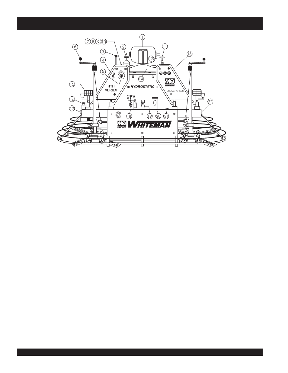
Figure 2. HTH44T Controls and Indicators (Front)
Figures 2 and 3 (pages 12 and 13) show the location of the
controls, indicators and general maintenance parts. The
function of each control, indicator or maintenance part is
explained below:
1.
Seat – Place for operator to sit. Engine will not start unless
operator is seated. Seat is adjustable.
2.
Steering Control (right side) -Allows the unit to move
in either a forward, reverse left or right direction.
3.
Throttle Control Lever – Controls the speed of the
engine. Move the hand lever forward to increase engine
speed (high), backwards to decrease engine speed (low).
4.
Light Switch – When activated, turns on six halogen
lights. Lights offer better visibility when working indoors.
5.
Ignition Switch – With key inserted turn clockwise to
start engine.
6.
Twin Pitch Control – Both pitch towers are linked
together. One crank may be turned to adjust the blade
pitch simultaneously or individually control for each set
of blades.
7.
Pre-Heat Indicator Light - Lights blue during engine
start-up. Indicates that engine glow plugs are being pre-
heated. Light will go off after approximately 10 seconds.
8.
Charge Indicator Light - Lights red when electrical
system is not charging properly.
9.
Water Indicator Light - Lights red when water
temperature is high.
10. Oil Indicator Light - Lights red when oil pressure is low.
11. Steering Control (left side) -Allows the unit to move in a
forward or reverse direction only.
12. Retardant Spray Control Button – When pressed allows
retardant spray to flow through the spray nozzle located
at the front of the machine.
13. Radiator/Filler Cap –Holds coolant or water necessary
to keep engine at a safe operating temperature. Remove
this cap to add water or antifreeze.
14. Kill Switch - Shuts down engine when operator is not
sitting in seat.
15. Lights – Low voltage halogen light.
16. Hydraulic Oil Filler Cap – Remove this cap to add
hydraulic oil.
17. Hydraulic Oil Sight Glass - Indicates the level of the
hydraulic oil in the reservoir.
18. Right Foot Pedal – Controls blade speed. Slow blade
speed is accomplished by slightly depressing the foot
pedal. Maximum blade speed is accomplished by fully
depressing the foot pedal.
19. Spray Nozzle – Spray nozzle for retardant.
20. Left Foot Riser – Operator foot rest pedal.
21. Fuel Gauge/Filler Cap - Indicates the amount of fuel in
the fuel tank. Remove this cap to add fuel.
22. Hydraulic Reservoir – Part of frame. Holds hydraulic oil
necessary for pump operation.