Htn/hto-31v — controls and indicators, Controls and indicators, Jto ride-on trowel – Multiquip JTO User Manual
Page 21
JTO RIDE-ON POWER TROWEL — OPERATION & PARTS MANUAL — REV. #5 (11/08/07) — PAGE 21
JTO RIDE-ON TROWEL
— CONTROLS AND INDICATORS
HTN/HTO-31V — CONTROLS AND INDICATORS
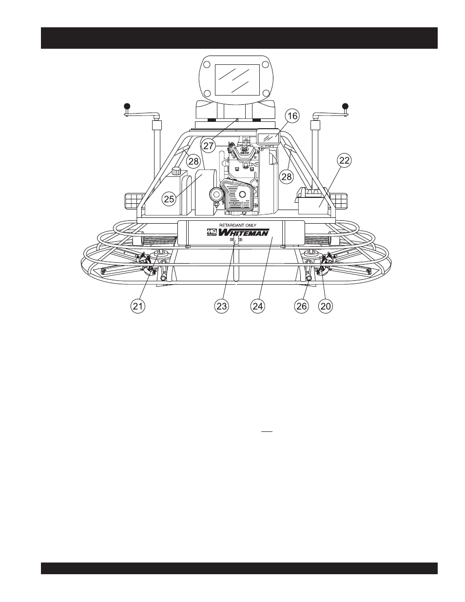
Figure 6. JTO Controls and Indicators (Rear)
20. Right-Side Spider – Consists (basic) of trowel arms,
blades, wear plate, and thrust collar etc.
21. Left-Side Spider – Consists (basic) of trowel arms, blades,
wear plate, and thrust collar etc.
22. Battery – Provides +12V DC power to the electrical system
23. Retardant Spray Motor – Used in conjunction with the
left spray control button.
24. Retardant Spray Tank – Holds 5 gallons of retardant.
25. Belt Guard – Encloses V-belts used in conjunction with
clutch.
26. EZ- Mover Boss – Back- side insertion point for EZ Mover.
Used when the transporting of the trowel is required.
27. Safety Kill Switch – Shuts down engine when operator is
not sitting in seat.
28. Lift Loops – Located on both the left and right sides of the
main frame. Used when the trowel must be lifted onto a
concrete slab.