Wrs-5200 — maintenance and adjustment procedures – Multiquip WRS5200 (CHINA) User Manual
Page 27
WRS 5200 RIDE-ON ROLLER SCREED — PARTS MANUAL— REV. 1# (12/14/01) — PAGE 27
WRS-5200 — MAINTENANCE AND ADJUSTMENT PROCEDURES
D.
STRAIGHTNESS OF STRIKE TUBES
Should strike tubes begin turning unevenly, contact your lo-
cal Multiquip representative for information on strike tube
straightening procedures.
To determine if a strike tube is turning uneven, place a 2 x 4
stud on the ground in the center of the strike tube as it sits
on the machine. Slide it close to the strike tube. Take the
strike tube motor off the end. Spin the strike tube by hand. If
a gap of over 1/8 inch shows up, contact your representa-
tive.
E.
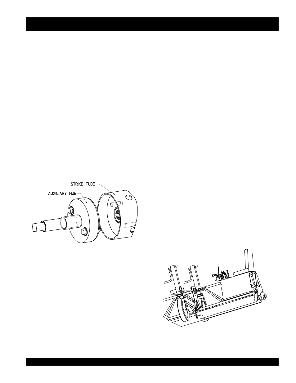
AUXILIARY HUB
An auxiliary hub, shown in Figure 16, for use with different
strike tubes is provided. Using the hub provides additional
combinations of roller screed lengths. Two ½ x 2-1/4 bolts
are provided for the purpose of bolting the hub to the strike
tube end.
Figure 16. Auxiliary Hub
Wiper bars should be adjusted to approximately 1/8” dis-
tance from the strike tube. The turnbuckle in the top pipe of
the 5’ section is also an adjustment for the wiper bar. This
adjustment can be used when the end of the wiper bar is too
close to the strike tube. IMPORTANT: Never let anything
rub grooves into the strike tube( i.e. wiper bars, concrete
forms, bolts, etc.) because those grooves in the strike tube
will be transferred into the concrete.
H.
STRIKE TUBE ADJUSTMENT NUT
The strike tube adjustment nut, shown in Figure 8, should
be adjusted so the inner edge of the strike tube next to the
middle bracket is spaced at about 1/16 to 1/8”. Note: The
strike tube will bottom out on the splined shaft when 1/16” is
left and further adjustment will bend the outer plate.
I.
SPLINED SHAFT SET SCREWS
Each roller screed comes with two middle brackets as shown
in Figure 9. Bearings mounted on the middle bracket hold
the splined shaft. The set screws in the bearings should be
checked for tightness occasionally.
J. REVERSING END CASTER BRACKETS
Figure 17 illustrates how end caster brackets can be re-
versed. This allows the roller screed to fit into areas close to
walls and columns.
Figure 17. Reversing Caster Brackets
F.
CHANGING THE HYDRAULIC FILTER
Usually the hydraulic filter and oil will be changed at the
same time. If not, creating a back suction on the hydraulic
tank will stop the flow of hydraulic oil when changing the
filters.
G.
SCRAPER AND WIPER BAR ADJUSTMENT
Scraper bars should be adjusted to approximately 1/8” dis-
tance from the drive tubes.