Wrs-5200 — assembly instructions – Multiquip WRS5200 (CHINA) User Manual
Page 16
PAGE 16 — WRS 5200 RIDE-ON ROLLER SCREED — PARTS MANUAL — REV. #1 (12/14/01)
WRS-5200 — ASSEMBLY INSTRUCTIONS
C. POWER UNIT ASSEMBLY
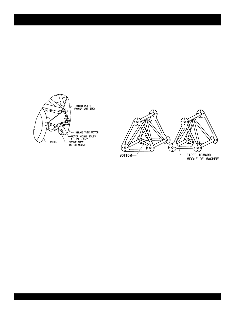
The power unit comes completely assembled. However,
before operating the screed, the hydraulic strike tube motor
from the power unit must be bolted to the motor mount, which
comes with the screed, as shown in Figure 3. This takes
two bolts, ½ X 1-1/2.
IMPORTANT: If you change power units, leave the strike
tube motor mount with the roller screed for the next power
unit
.
D. ROLLER SCREED ASSEMBLY
2. Description
The WRS 5200 Ride-On Roller Screed is made up of truss
sections (Figure 4) which vary in length from 3 to 9 feet.
These truss sections support the 6 inch tubing (strike tube)
which runs along the front of the machine. This strike tube
comes in four different lengths, 8, 14, 16 and 18 feet. By
coordinating the truss section and strike tube lengths, vari-
ous roller screed lengths can be assembled.
Figure 4. Truss End Plate
Table 2.
ROLLER SCREED ASSEMBLY
LENG.(FT)*
TRUSS SECTION (FT)**
LETTER CODE ON TRUSS
SECTION
STRIKE TUBE(FT)
18
5,8,5
L,RM8,R
18
22
5,9,3,5
L,L14,R8,R
14,8
26
5,4,9,3,5
L,L18,L14,R8,R
18,8
28
5,9,3,6,5
L,L14,R8,R14,R
14,14
30
5,9,8,3,5
L,L14,RM8,R8,R
14,16
32
5,9,3,6,4,5
L,L14,R8,R14,R18,R
14,18
36
5,9,8,3,6,5
L,L14,RM8,R8,R14,R
14,8,14
40
5,9,8,3,6,4,5
L,L14,RM8,R8,R14,R18,R
14,8,18
44
5,9,8,8,3,6,5
L,L14,LM8,RM8,R8,R14,R
14,16,14
44
5,4,9,8,3,6,4,5
L,L18,L14,RM8,R8,R14,R18,R
18,8,18
48
5,9,8,8,3,6,4,5
L,L14,LM8,RM8,R8,R14,R18,R
14,16,18
52
5,4,9,8,8,3,6,4,5
L,L18,L14,LM8,RM8,R8,R14,R18,R
18,16,18
* Actual concrete form width should be at least 2 foot less than screed length.
** Left side of Table I in the truss section represents the power unit end
Table 2 shows the different combination of truss
sections and strike tube lengths to get the desired
roller screed length. Dimensions are in feet
Figure 3. Strike Tube Motor Assembly