Maintenance – Multiquip LS-600P User Manual
Page 48
page 48 — MaYCO LS600p CONCReTe pUMp • OpeRaTiON MaNUaL — Rev. #0 (05/13/13)
Accumulator Circuit
The accumulator circuit has two functions in the hydraulic
system.
The accumulator circuit furnishes the hydraulic pressure
to cycle the shuttle tube.
The accumulator circuit also furnishes the pilot pressure
necessary to activate the hydraulic system.
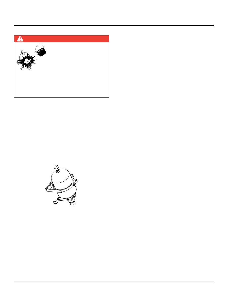
The accumulator circuit is equipped with a bladder type
accumulator (Figure 55) charged with 1100 PSI of dry
nitrogen. The accumulator stores one gallon of hydraulic
oil, which is, under 1750 PSI of pressure.
Figure 55. Accumulator
When the pump cycles, a part of the stored oil is released
to the shuttle cylinder. This released oil pressure assures
the shuttle tube has enough force to shear the cylinder of
concrete passing from the concrete cylinder to the concrete
delivery line during the cycle phase.
Checking Accumulator Bladder Pressure
The normal accumulator charge pressure should be
approximately 1100 PSI. To check the accumulator
pressure:
DANGER
Improper accumulator charging
can result in an explosion causing
serious injury or death! Never
use oxygen or compressed air
to charge the accumulator! Only
qualified personal should perform
this procedure. Use only dry nitrogen to charge the
accumulator. Contact your Mayco service department
or your local Hydac representative for proper charging
procedure
MAIntEnAncE
1. Start the engine and stroke the pump. The accumulator
pressure gauge (Figure 30) should read 1750 PSI.
2. To determine the actual accumulator PSI, stop the
engine and observe the pressure gauge. As the PSI
reading slowly decreases, it will reach a point where
there will be a sudden drop in the PSI. The PSI reading
should be taken just prior to this sudden drop. If you
do not read 1100 PSI, the accumulator may require
charging or bladder replacement.
Wear Plate and Cutting Ring
Due to the abrasive nature of concrete, it is normal for the
cutting ring to wear on its sides as it shears through the
concrete inside the hopper. The metal-to-metal friction and
the abrasiveness of the concrete will cause extreme wear
and reduce sealing capability between the cutting ring and
wear plate.
If the two components do not properly seat against each
other, slurry will pump into the hopper rather than out the
discharge line. See Figure 56. This condition can easily
be observed.
1. The sudden change of the level of concrete inside the
hopper during each pumping stroke
2. Concrete slurry squirting into the air from the hopper
(Volcano effect)
3. When the output volume at the end of the delivery line
decreases in pressure
4. Unusual frequent material packs in the Shuttle tube
It is important that the wear components be inspected
weekly for proper sealing. Failure to inspect will eventually
cause severe damage to the nun-plate and material
cylinders. Visually inspect wear plate and cutting ring to
ensure surfaces are sealed against each other.
If a deep groove or a wide space has developed on the
sealing surfaces, it is time for replacement. Due to the
motion of the
shuttle tube, the cutting ring experiences
a quicker rate of wear as opposed to the wear plate. The
wear ring typically requires replacement two times per wear
plate (2 to 1). When replacing the wear ring, also replace
the rubber energizer ring.