MTD 190-751-OEM User Manual
Page 4
4
TOOLS REQUIRED FOR ASSEMBLY
(2)
7/16" Wrenches
(2)
1/2” Wrenches
(1)
3/4” Wrench
(2)
15/16” Wrenches
REMOVAL OF PARTS FROM TRACTOR
1. Remove any rear mounted attachments which
may be installed on your tractor
2. Mark and save all removed parts.
ASSEMBLING BRACKETS TO TRACTOR
FAST-ATTACH TRACTORS
3. Skip to ASSEMBLING THE BASE
STANDARD FRAME TRACTORS
4. Remove top four bolts from rear of tractor frame.
See figure 1.
5. Attach LH and RH adapter brackets to rear of tractor
frame using bolts removed in step 4. See figure 2.
FIGURE 1
FIGURE 3
FIGURE 2
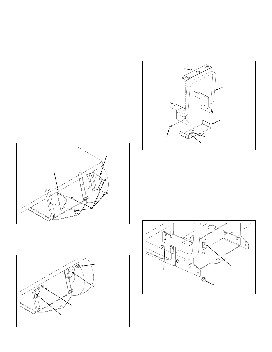
ASSEMBLING THE BASE
7. Assemble the drawbar bracket to the base
assembly using four 5/16” x 1” hex bolts, 5/16”
lockwashers and 5/16” hex nuts. See figure 3.
8. Attach the tool bracket to the base assembly
using four 5/16” x 1” hex bolts, 5/16”
lockwashers and 5/16” hex nuts. See figure 3.
6. Assemble a shoulder bolt and a 1/2” jam nut to each
adapter bracket. See figure 2.
ATTACHING BASE TO TRACTOR
FAST ATTACH TRACTORS
9. Hook the base assembly under the shoulder bolts on
the sides the tractor frame using the
front
notches in
the base assembly. Align the hole in the bottom of
the base assembly with the hole in the tractor draw-
bar. Insert the 5/8” x 1-3/4” hex bolt and secure it with
the 5/8” hex nut. See figure 4.
FIGURE 4
BOLTS FROM
TRACTOR FRAME
L.H. ADAPTER
BRACKET
R.H. ADAPTER
BRACKET
SHOULDER
BOLT
1/2" JAM NUT
1/2" JAM NUT
SHOULDER
BOLT
5/16" x 1"
HEX BOLT
5/16" HEX NUT
5/16" LOCK WASHER
DRAWBAR
BRACKET
TOOL BRACKET
BASE
ASSEMBLY
5/8" HEX NUT
5/8" x 1-3/4"
HEX BOLT
SHOULDER BOLT