Installation continued, Motorguide wiring diagrams – MotorGuide BATTERY CHARGERS User Manual
Page 9
7
INSTALLATION CONTINUED
7. Run your cables free from sharp objects and hold each of them in place with cable ties.
Coil excess cable, do not cut or shorten the length of the cables as there are in-line
fuses located 4 inches from the end of each positive (red) cable. These fuses are in place to
protect the charger and output cables in the event of a short or reverse polarity.
8. Connect the DC output cables as illustrated on page 8. Make sure the (black or yellow)
wires are connected as illustrated to the negative side of the battery and the red wires are
connected to the positive side of the battery.
9. Make sure all DC connections are tight and correct.
10. Locate the AC power cord in an open-air area of your boat at least 21 inches from the
charger, batteries and fuel fill lines.
11. Connect a heavy duty U.L. approved extension cord to the battery charger first. After
connecting the extension cord to the charger then proceed to plug the extension cord to
a nearby 120VAC GFCI protected (Ground Fault Circuit Interrupt) outlet. Always remove the
extension cord from the 120VAC outlet first when charging is completed, followed by
unplugging the charger.
You are now connected and charging your batteries. View the LED indicators. Assuming your
batteries are discharged you should observe both the blue "Power" LED and the red "Charging"
LED on, indicating charging mode is in process.
I N S T A L L A T I O N
Note 1: One bank cable connects to no more than one battery
I N S T A L L A T I O N
MOTORGUIDE WIRING DIAGRAMS
12
When connecting each jacketed battery charger cable, make sure it is connected
to only one 12 VDC battery and observe the polarity and color of all connections:
Red Wire = + (Positive) Battery connection
Black Wire = - (Negative) Battery connection
The black wire can never be connected to a terminal with red wires. Only black.
Installation
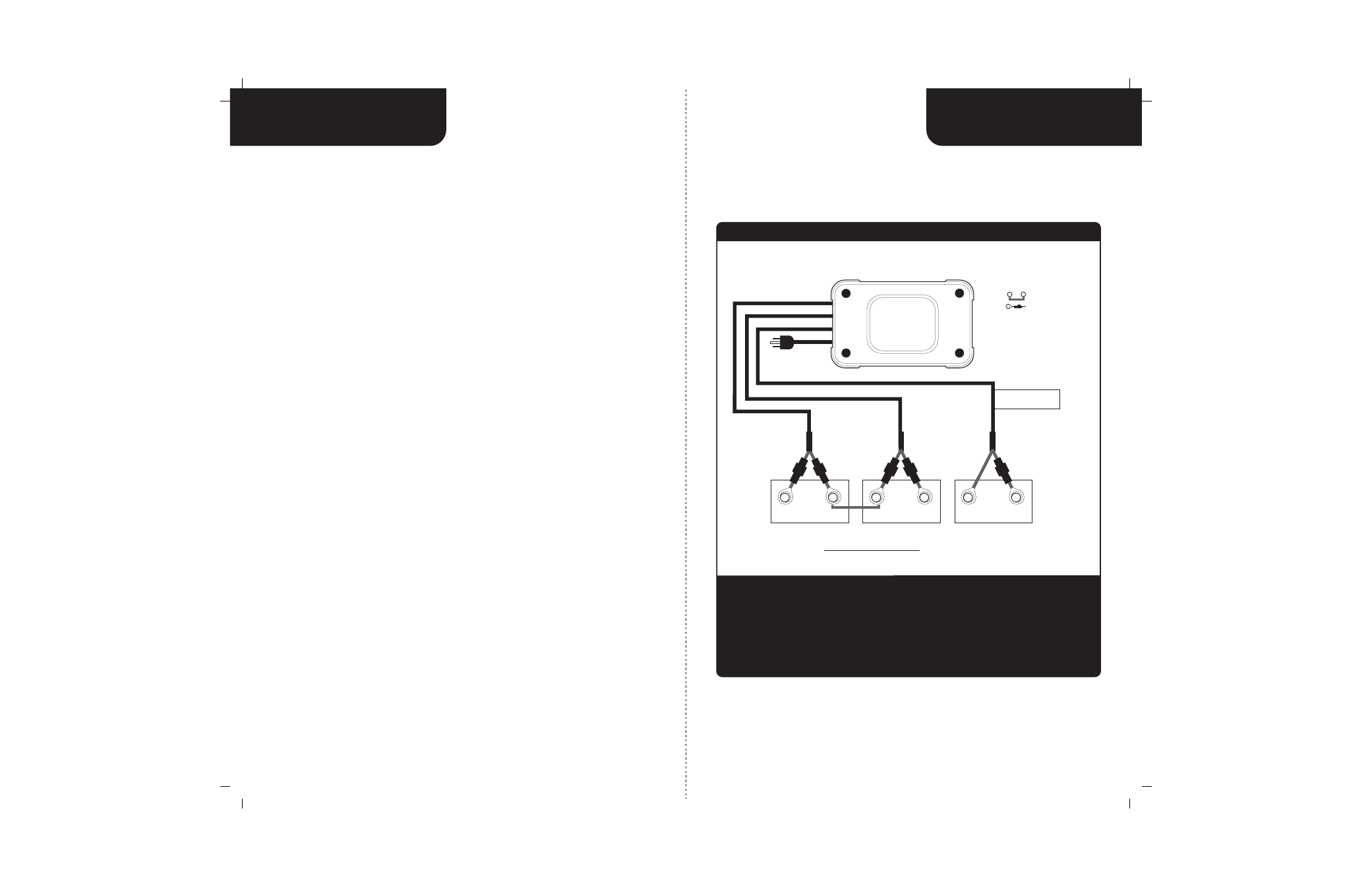
Triple Output Charger for 3 12V Batteries
Important: The pair of red and black wires in 1 cable jacket MUST GO TO THE SAME 12VDC battery.
12 VDC Engine
Crank Battery
Two 12 VDC Batteries connected with a series
jumper for a 24 VDC Trolling Motor
24 VDC Trolling Motor Battery Configuration with (2) 12 VDC Batteries Connected
with a Series Jumper Plus Dedicated 12 VDC Engine Start Battery
Top View
of Battery
red
black
+
_
red
black
red
black
Cable 1
Bat 1
Bat 2
Bat 3
Cable 2
Cable 3
For Engine Battery use
this Bank Cable Only
+
_
+
_
Indicates Jumper Series
Note:
Indicates Fuse
MotorGuide
5/5/3
Output 2
AC power
Output 1
Output 3