Motorguide wiring diagrams – MotorGuide BATTERY CHARGERS User Manual
Page 11
I N S T A L L A T I O N
MOTORGUIDE WIRING DIAGRAMS
10
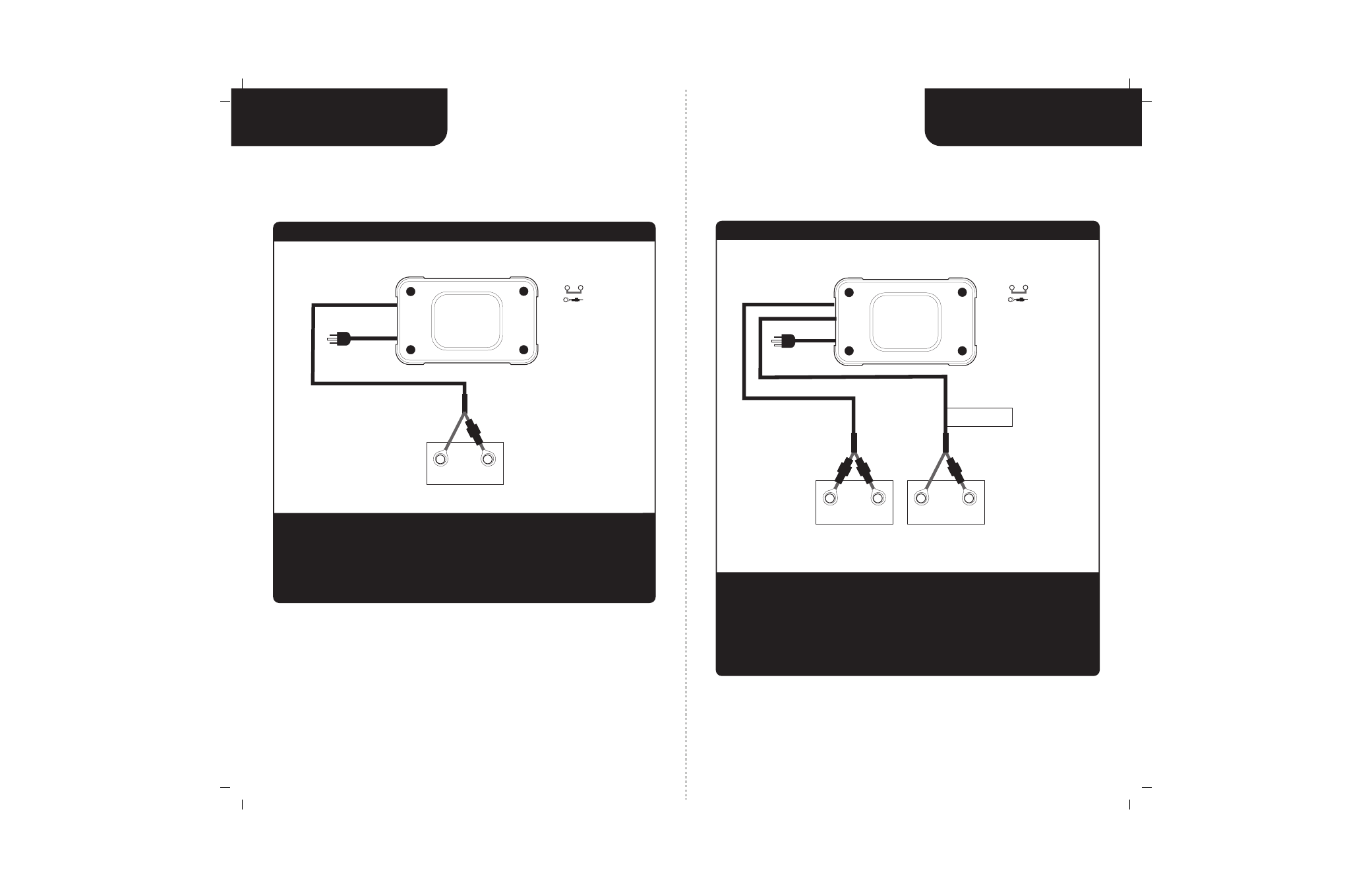
When connecting each jacketed battery charger cable, make sure it is connected
to only one 12 VDC battery and observe the polarity and color of all connections:
Red Wire = + (Positive) Battery connection
Black Wire = - (Negative) Battery connection
The black wire can never be connected to a terminal with red wires. Only black.
Installation
Dual Output Charger for 2 12V Batteries
Important: The pair of red and black wires in 1 cable jacket MUST GO TO THE SAME 12VDC battery.
12 VDC Trolling Motor + Engine Crank Battery Configuration with (2) 12 VDC Batteries
12 VDC Engine
Crank Battery
Top View
of Battery
red
black
+
_
red
black
+
_
Bat 2
Bat 1
Cable 2
Cable 1
For Engine Battery use
this Bank Cable Only
12 VDC Trolling
Motor Battery
Indicates Jumper Series
Note:
Indicates Fuse
MotorGuide
5/3 and 5/5
Output 2
AC power
Output 1
MOTORGUIDE WIRING DIAGRAMS
I N S T A L L A T I O N
9
red
black
+
_
When connecting each jacketed battery charger cable, make sure it is connected
to only one 12 VDC battery and observe the polarity and color of all connections:
Red Wire = + (Positive) Battery connection
Black Wire = - (Negative) Battery connection
The black wire can never be connected to a terminal with red wires. Only black.
Installation
Single Output Charger for 1 12V Battery
Dedicated 12 VDC Trolling Motor or Engine Battery Configuration
Engine Crank or 12V Trolling Motor Battery
Top View
of Battery
Indicates Jumper Series
Note:
Indicates Fuse
Bat 1
Cable 1
MotorGuide
5
Output 1
AC power