Memmert PM 500 Self Drying Vacuumpump (Generation 2003) User Manual
Page 5
disposed of.
Ī Use only original KNF replacement
parts.
Parts and tools required:
½ 1 Service Set (see section 7)
½ Screwdriver blade width 2 mm
½ Phillips screwdriver No. 2
½ Felt-tip pen.
Change the diaphragms and valve pla-
tes/sealings in the following sequence:
a) Preparatory steps
b) Removing pump head
c) Changing diaphragm
d) Changing valve plates/ sealings
e) Refitting pump head
f) Final steps.
̈ The position numbers in the
following text refer to fig. 2.
a.) Preparatory Steps
ᕡ Shut down system (see section 4.2)
including disconnecting the pump
from the power source (pull out
plug of pump).
ᕢ Remove tubing from the inlet and
outlet connectors of the pump.
» On the pneumatic head connec-
tions, loosen one of the union nuts
by hand. Then slightly loosen the
angle-fitting in the pump head by
turning it anticlockwise, so that the
connecting tube can be pulled out
¿ Undo the screws that hold the
fan cover (see fig. 1) and remove
the fan cover from the motor.
b) Removing pump head
(for each head separately)
³ Mark the position of top plate ቢ,
head plate
ባ, intermediate plate
ቤ, and housing ብ relative to each
other with a felt-tip pen. This is to
ensure that the parts will be re-
assembled cor rectly at a later
stage.
· Undo the eight screws ቦ and lift
the pump head off the housing
ብ.
Ī
The solenoid valve of the
drying system remains fitted
in this situation.
c) Changing diaphragm
³ Position the pump so that the dia-
phragm surface is upwards.
· Turn the fan to bring the structured
diaphragm
ቧ to top dead centre.
» Using a small screwdriver, bet-
ween the housing and the outer
edge of the structured diaphragm,
carefully lift the edge of the dia-
phragm lightly upwards at one
point (making sure not to damage
the housing). Now grip the edge of
the diaphragm on opposite sides,
unscrew it by turning anti-clock-
wise.
¿ Take the diaphragm spacer(s) ቨ off
the connecting rod
ቩ and retain
them.
´ Check that all parts are free from
dirt and clean them if necessary.
² Put the diaphragm spacer(s) ቨ
on the thread of the new dia-
phragm.
ᕧ Fit the new structured diaphragm
ቧ: hold the connecting rod ቩ with
one finger, and gently screw in
(clockwise) the structured dia-
phragm with diaphragm spacers.
º Turn the fan until the structured
diaphragm is at the top dead cent-
re. Using a small screwdriver, bet-
ween the housing and the outer
edge of the structured diaphragm,
carefully lift the edge of the dia-
phragm lightly upwards at one
point. Now grip the edge of the dia-
phragm on opposite sides (do not
overstretch the diaphragm!) and
tighten the structured diaphragm
clock-wise.
d) Changing valve plates/sealings
³ Undo the two screws ቪ.
· Separate the head plate ባ with
top plate
ቢ from intermediate
plate
ቤ.
» Remove the valve plates/sealings
ቭ from the intermediate plate.
¿ Check that the valve seats, the
head plate and intermediate plate
are clean. If scratches, distortion,
or corrosion are evident on these
parts they should be replaced.
´ Lay the new valve plates/sealings
ቭ in the recesses in the interme-
diate plate. The valve plates/sea-
lings for suction and pressure sides
are identical, as are upper and
lower sides of the plates/sealings.
e) Refitting pump head
³ Turn the fan to bring the structured
diaphragm
ቧ to medium position.
· Place the intermediate plate ቤ,
with valve plates/sealings
ቭ on
the housing, in the position indica-
ted by the felt-tip pen marking.
» Place the head plate ባ on the
intermediate plate
ቤ in the posi-
tion indicated by the felt-tip pen
marking.
¿ Place top plate ቢ in position
PM 16527-860.3-2.00 e 11/05
4
ቦ ባ ቤ
ቭ ቢ
X
X
ብ ቧ ቨ ቩ
ቪ ቫ
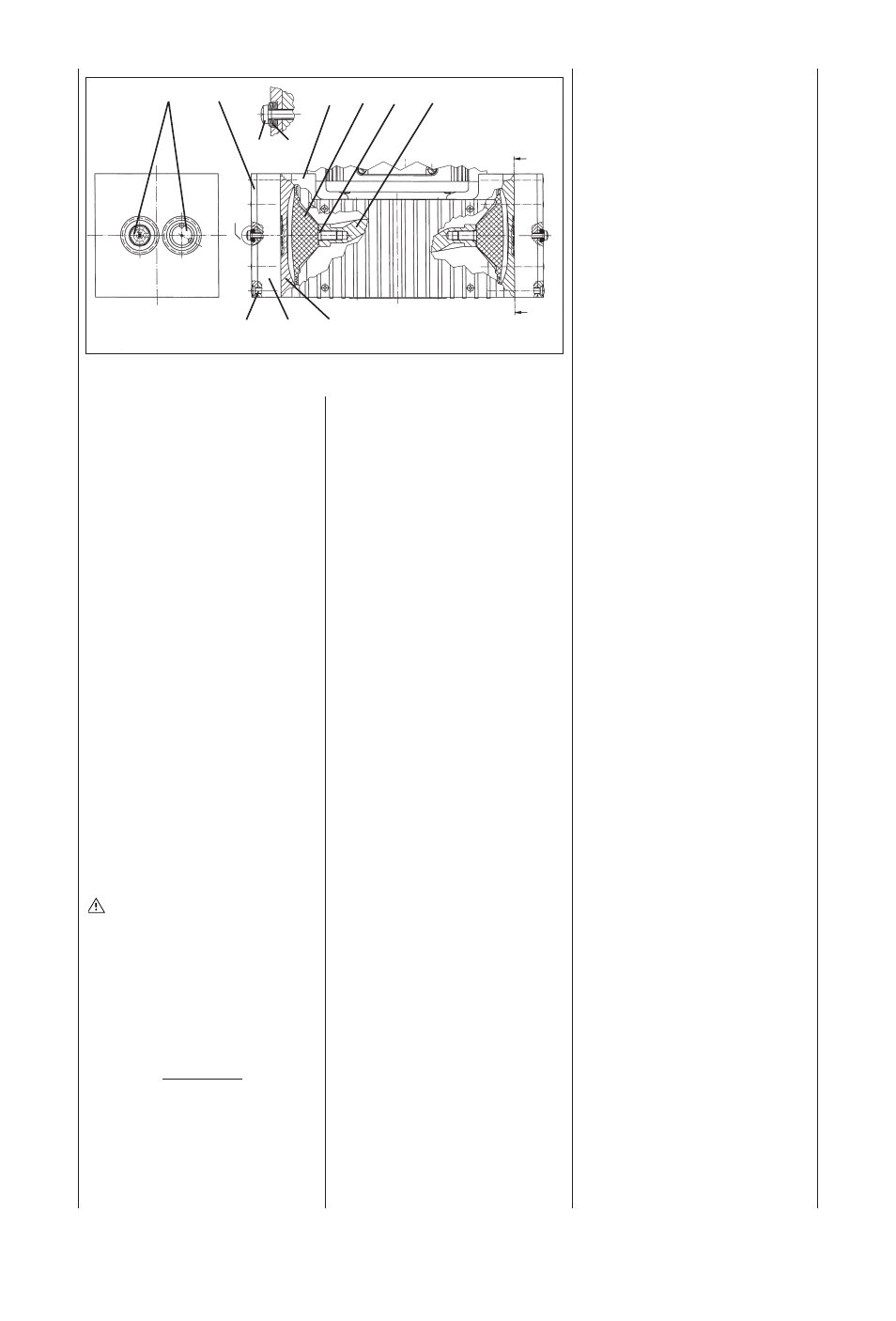
Fig. 2: Cross section of pump heads (symbolic)
Specification
Pos Description
ቢ Top plate
ባ Head plate
ቤ Intermediate plate
ብ Housing
ቦ Cross recessed raised counter-
sunk head screw
ቧ Structured diaphragm
ቨ Diaphragm spacers(s)
ቩ Connecting rod
ቪ Cross recessed raised cheese
head screw
ቫ Disk spring
ቭ Valve plate/Sealing