Memmert PM 500 Self Drying Vacuumpump (Generation 2003) User Manual
Page 4
pressure. This also applies when
the pump restarts after the power
has been cut off for a short period.
The components to be connected
to the pump must be designed to
withstand the pneumatic data of
the pumps (see Section 8).
The maximum permissible opera-
ting pressure (1 bar g) must not be
exceeded.
½ To prevent the maximum permis-
sible operating pressure being
exceeded, restriction or control of
the air or gas flow should only be
carried out in the suction line.
½ If restriction or control of the air or
gas flow is made on the pressure
side ensure that the maximum per-
missible operating pressure is not
exceeded.
½ When the pump is at a standstill
the inlet and the outlet must be at
normal atmospheric pressure.
Ensure the pump outlet is not clo-
sed or restricted.
½ Diaphragm and valve plates are the
only parts subject to wear. Wear is
usually indicated by a drastic
reduction in the pneumatic perfor-
mance. When replacing parts pro-
ceed as described in section 5.
½ Ambient conditions: see chapter
1.3.
4.2 Operation
Taking the pump into operation
ᕡ Plug the mains plug of the pump
into a properly installed safety
socket.
ᕢ Switch the pump on at the pump
mains switch (see fig. 1).
ᕣ If cyclic drying of the pump heads
is required in the current evacu-
ation process, switch the drying
system on at the mains switch of
the control system (not included in
scope of delivery).
Ī The drying system should only
be switched on if a container
has been attached to the pres-
sure line of the pump which will
catch the condensate; other-
wise the condensate will flow
out uncontrolled.
Check:
³ Tubing for correct tubing.
· Electrical connections for correct
connection.
After the evacuation/process has been
completed, take the pump out of ope-
ration:
ᕡ Purge the pump including the
connecting hoses with air at full
flow rate for about 5 minutes.
ᕢ If the drying system is switched
on:
Switch the drying system off at the
mains switch of control system
(not included in scope of delivery).
ᕣ Switch the pump off at the mains
switch of the pump.
ᕤ Pull the mains plug of the pump out
of the socket.
5. Servicing:
Changing Diaphragms and Valve
Plates/Sealings
The diaphragms in both pump heads
should be changed at the same time.
When diaphragms are changed, valve
plates/sealings should also be repla-
ced. If the diaphragms are not changed
in both heads at the same time or dia-
phragms and valve plates/sealings are
not changed at the same time the
nominal performance of the pump is
not guaranteed after the service.
If a pump has been used for
aggressive or toxic substances or
other types of substances which
are hazardous, hazardous to health,
or injurious, the following points
must be observed:
1.) Clean the pump and its compo-
nents before servicing.
2.) Ensure that the service personnel
is not subject to a health hazard.
Apply the safety and protection
measures that are necessary for
the medium that has been handled
by the pump (example: the use of
protective gloves).
3.) Ensure that discarded parts and
materials are safely and correctly
PM 16527-860.3-2.00 e 11/05
3
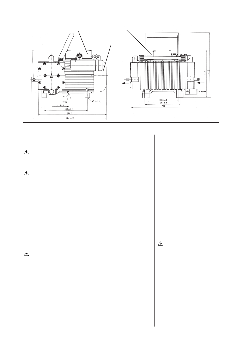
Fig. 1: Pump PM 16527-N 860.3-2.00
Fan cover
Connecting box of the pump
Mains switch
for tube ID 10
6 mm deep
blue
brown
voltage valve